
Hot Runners: A View from the Bottom Up
Addressing hot-runner benefits, improvements, and everyday issues from the perspective of decades of experience with probably every brand on the market. Part 1 of 2.


I started working in plastics in 1988 and have seen hot runners evolve drastically over the past few decades. I built hot runners from raw blocks of steel back in the day; I have built numerous custom tips and have maintained just about any hot-runner brand you can name in the process of managing thousands of molds a year built all over the world. I mention my experience to verify that I have been hands-on maintaining hot runners and solving issues, not sitting behind a desk reading books. The purpose of this column is not to promote or discourage the use of hot runners but to provide a better understanding of them from a user viewpoint in the daily injection molding environment.
With advances in technology, hot runners have many more uses today than they did years ago. They are used to eliminate the cold sprue and runner, which can save you money on scrap when regrind is not an option.


Hot runners allow direct gating onto the part with a low-vestige tip or valve gate and eliminate the need for three-plate runner systems. They also allow you to gate on the outside edge of the part when it is centered on the mold.
On larger parts where knit lines or flow lines are a concern, you can use sequential valve gates to control the flow and move the knit lines. You can use multiple hot drops to reduce fill pressures. And they can be used to eliminate long cold runners to reduce the pressure loss and improve the process window.
So hot runners have many applications and can be very beneficial to the process, providing savings in cycle time and elimination of cold runner and sprue. Of course, hot runners can add a significant cost to the tool up front and therefore need to be justified economically. But the payback can be very significant On tools that run higher volumes and/or higher-cost resins.
Hot runners do add some complexity to the mold and require added maintenance; but improved designs have drastically reduced issues with hot runners over the years. The terrifying sight of a hot-runner pocket and wire channels packed full of plastic can bring instant heartburn. This sight was more common years ago, but in my arena, managing thousands of preventive-maintenance operations (PMs) and repairs a year, it is not so common anymore. I will touch base on what had the biggest impact on this in Part 2 next month.
A ‘SIMPLE’ VIEW OF HOT RUNNERS
I want to simplify the understanding of the hot runner and its function. First, think of it as an extension of the molding machine itself. Its purpose is to keep the plastic molten at a proper temperature on its path to the cavity. So basically it’s just a piece of heated steel with a round channel in it for the melt to flow through. Ideally, this channel would be running at the exact temperature on the controller, free of obstacles such as dead spots or components that could create hangups and cause scrap issues with color changes or contamination.
The flow channel needs properly placed heaters and thermocouples to ensure that the correct temperature is maintained. The thermocouple itself is the most critical component. It is what reads the hot-runner temperature and tells the controller how much current to send to the heater to maintain the set temperature. In most cases when there is an issue with temperature, the thermocouple is the root cause, not the heater.
A heater is basically like a light bulb—it’s either working or burnt out, but there are times when it appears to be functioning but is not able to come up to temperature. I will get into how to verify the function of the heater in the press by measuring resistance/ohms.
If a thermocouple is loose or not held tight against the steel whose temperature it is supposed to read, the thermocouple will be reading the ambient air temperature instead, causing the controller to send excessive current to the heater and result in extreme overheating. I’ve seen this situation cause material in hot runners to spew smoke while the controller was showing that zone to be under the set temperature. I have also seen this happen when the thermocouple and heaters were not wired to the correct zones on the connection plugs.
Years ago, heaters with integrated thermocouples were more common, but they are not reliable for providing accurate temperature of hot-runner components. So you need to understand how critical the thermocouple and its placement are. Fortunately, most hot-runner manufacturers today are very good at thermocouple and heater placement to maintain accurate temperature without cold or hot spots.
I have also tried to stay away from the old analog-style hot-runner controllers. The newer electronic controllers are much more accurate and provide a smoother flow of amps. I have seen a few cases where just changing controllers to the newer technology eliminated issues with parts.
One case involved brown streaks on a polycarbonate part. We spent a lot of time working on the hot runner and process with no improvements, but the controller was the issue and when we changed the controller our issue disappeared. Another case concerned a part that had a specification on reflectivity. We were getting erratic results, but with a controller change our issue was eliminated.
TIPS ON TIPS
Many times over the years, hot runners have been a source of concern over dead spots where the material can hang up and degrade. With today’s hot-runner designs, this is not an issue in most cases.
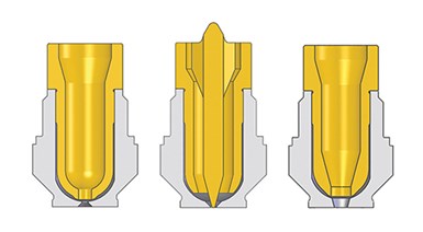
Hot-runner tips can have a great influence on part cosmetics. Left to right: sprue style, low-vestige tip, and valve gate.
Photo Credit: Incoe
The one area of the hot runner that causes the most issues with part cosmetics is the hot-drop tip. The other area to consider is the orifices on the hot runner and on the nozzle tip. Hot-runner designs have seen many technical advances in tip designs and styles, which have helped with cycle times and gate vestige, but these components are obstacles in the flow path and can cause hangups.
There are three general styles of hot-drop tip designs, with many variations of each: The low-vestige tip, straight-through sprue style, and the valve gate.
• The low-vestige tip is used to direct gate onto the part with minimal vestige, and also is used on cold runners to reduce stringers. But I have found, in most cases, that this tip style is not a necessity. It can increase fill pressures (pressure loss) and contribute to color issues when running multiple colors. This tip style will also plug easier, as the orifice has less volume/area. This can be a big headache when running regrind with this style of tip.
• The straight-through tip style is usually the least problematic for color changes and contamination, without as many areas for the material to hang up. But even with some of the new designs today, and with an insulating gap, even a sprue-style tip can create problems. Most systems provide components to fill these gaps, commonly known as color seals.
• Valve gates are used to directgate onto the part with minimal vestige and are also used to control the flow when using multiple valve gates. Because they can be shut off independently you can control flow fronts and knit-line locations.
ABOUT THE AUTHOR
Randy Kerkstra has been in the plastics industry for more than 26 years, occupied frequently with troubleshooting injection molding. He is currently a tooling manager for a large, multi-plant molding and manufacturing company. Contact: kbmoldingsolutions@gmail.com.


Related Content

Improve The Cooling Performance Of Your Molds
Need to figure out your mold-cooling energy requirements for the various polymers you run? What about sizing cooling circuits so they provide adequate cooling capacity? Learn the tricks of the trade here.
Read More
Back to Basics on Mold Venting (Part 1)
Here’s what you need to know to improve the quality of your parts and to protect your molds.
Read More
Where and How to Vent Injection Molds: Part 3
Questioning several “rules of thumb” about venting injection molds.
Read More
How to Mount an Injection Mold
Five industry pros with more than 200 years of combined molding experience provide step-by-step best practices on mounting a mold in a horizontal injection molding machine.
Read MoreRead Next

For PLASTICS' CEO Seaholm, NPE to Shine Light on Sustainability Successes
With advocacy, communication and sustainability as three main pillars, Seaholm leads a trade association to NPE that ‘is more active today than we have ever been.’
Read More
Making the Circular Economy a Reality
Driven by brand owner demands and new worldwide legislation, the entire supply chain is working toward the shift to circularity, with some evidence the circular economy has already begun.
Read More
Beyond Prototypes: 8 Ways the Plastics Industry Is Using 3D Printing
Plastics processors are finding applications for 3D printing around the plant and across the supply chain. Here are 8 examples to look for at NPE2024.
Read More