Stress: Diagnose It Before It Ruins Your Parts
Residual stress is an inherent result of plastics manufacturing processes and occurs when molten polymer is cooled and shaped.
Residual stress is an inherent result of plastics manufacturing processes and occurs when molten polymer is cooled and shaped. Sometimes, these stresses are intentionally produced to impart desirable characteristics, such as in oriented PET films and bottles. But in most cases, residual stress is an invisible and insidious problem that can cause field failures and leave a manufacturer exposed to product-liability claims. It can reduce product quality and erode a company’s bottom line due to increased scrap and rejects. High levels of stress also lower a product’s impact strength and can contribute to environmental stress cracking and diminished performance at high or cycling temperatures.
Some common causes of harmful residual stress in molded, thermoformed, and extruded products are differential cooling rates, non-uniform temperature or flow rate, material contaminants, mechanical loading, thermal cycling during transport and storage, inadequate or non-uniform annealing, and sharp corners or protrusions that cause localized stress concentrations.
When the stress profile within a plastic part is known, adjustments in the process, material, or part design may be made to eliminate these stresses or reduce them to an acceptable level.
Effects of residual stress
Problems caused by residual stress in polymers generally fall into one of the following categories:
- Distortion: If you are experiencing field failures of blister packs or similar products, the problem may be due to stress-relaxation induced distortion. This occurs when parts with excessive residual stress go through post-manufacturing thermal cycles, such as sterilization or heat sealing. It can also happen when products are exposed to varying ambient temperatures in transportation and warehousing. The part warps or shrinks, causing packaging failures, loss of product, or packages that are visually unattractive.
- Cracking and crazing: Cracking under normal load conditions is usually evidence of excessive residual stress. Crazing is the appearance of many fine microcracks. Exposure to chemicals can exacerbate these conditions, which may not be apparent during production and QC inspection. Polystyrene parts dipped in kerosene, for example, will craze quickly in stressed areas.
- Deterioration of optical properties: Residual stress changes a material’s refractive index, thus introducing optical distortion. This can adversely affect the appearance of products such as bottles and windows and the performance of products such as plastic lenses and compact discs.
- Creep and other changes in mechanical properties: Creep occurs when residual stresses cause initial load deformation to become permanent. Drawing, forming, and cooling procedures introduce directional stresses in oriented polymers that can lead to undesirable changes. An extruded tube or sheet, for example, may show decreased performance in the unstretched direction. Likewise, if processed at too low a temperature, the part can shrink in the machine direction and expand in the cross-machine direction.
Measuring residual stress
Photoelastic evaluation of stress and orientation, either during production or in quality control, can help processors identify potential field failures before parts leave the factory. Even in well-designed parts, examination of a transparent product under polarized light will typically reveal stress gradients and orientation changes due to manufacturing or finishing processes.
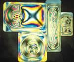
When viewed with polarized light, stressed areas of polymers are visible to the eye as a series of multicolored bands or fringes. This fringe pattern, sometimes referred to as birefringence, can be interpreted as varying levels of stress at a specific point and in a particular direction through the material.
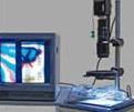
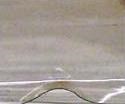
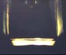
The instrument most commonly used to evaluate stresses is a simple polariscope, or “strain viewer,” consisting of a white light source and suitable polarizing elements. The thermoformed medical blister packs shown in Fig. 1 were evaluated using the instrument shown in Fig. 2. This type of qualitative evaluation can be used to compare stresses in two identical parts and/or to survey stress distribution in a part.
When polarized light passes through transparent or translucent plastic, the components of the light wave that are parallel and perpendicular to the direction of the stress propagate through the plastic at different speeds. This effect is known as “retardation” and is proportional to the degree of stress in the material at that point. When light that has experienced retardation is viewed with a polariscope, the two components of the original light beam interfere with one another, resulting in a visible display of varying colors and intensities (fringes) wherever stress is present in the material.
In simple cases, the color fringes can be used to evaluate residual stress, since each color band correlates to the degree of stress in the inspected sample. A retardation vs. color chart can be used to interpret the observed pattern (see table). In practice, however, the procedure requires a trained eye and can never be more than an empirical technique, best reserved for pass/fail inspection.
Materials that exhibit very low stresses, very high stresses, or complex geometries and high stress gradients require quantitative measurement using visual or PC-based instruments known as polarimeters.
A basic method for measuring (rather than just observing) stress is described in ASTM D4093. This standard test method uses a polariscope in conjunction with an accessory called a “compensator” or “measuring wedge” (Fig. 4). This precision device optically converts the mysterious and often complex stress color pattern into an easy-to-discern black line that can be used to arrive at a reliable and reproducible measurement. A calibrated scale on the compensator supplies a quantitative reading of retardation, which can then be used as a gauge of the stress value or can be converted into units of birefringence or stress (MPa or psi) by means of a simple equation.
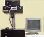
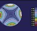
In addition to visual methods of measuring stress, PC-based instruments, which replace the human observer with computer vision, are now available in both on-line and off-line configurations (Figs. 5 and 6). These automated systems take the guesswork out of birefringence measurement and are used where fast, accurate results are required. One leading polymer film manufacturer, for example, has five of these systems installed at plant locations in the U.S., Europe, and Asia.
|
COLOR SEQUENCEa OBSERVED VS. RETARDATION VALUE
|
|||
|
Color |
Retardation (δ), nm | Retardation, N fringesc | 
|
| Black: Zero order fringe | 0 | 0 | |
| Gray | 160 | 0.28 | |
| White-Yellow | 260 | 0.45 | |
| Yellow | 350 | 0.60 | |
| Orange (Dark Yellow) | 460 | 0.79 | |
| Red | 520 | 0.90 | |
| Indigo-Violet: Tint of passage #1b (1st order fringe) | 577 | 1.00 | |
| Blue | 620 | 1.06 | |
| Blue-Green | 700 | 1.20 | |
| Green-Yellow | 800 | 1.38 | |
| Orange | 940 | 1.62 | |
| Red | 1050 | 1.81 | |
| Indigo-Violet: tint of passage #2 (2nd order fringe) |
1150 | 2.00 | |
| Green | 1300 | 2.25 | |
| Green-Yellow | 1400 | 2.46 | |
| Pink | 1500 | 2.60 | |
| Violet: tint of passage #3 (3rd order fringe) |
1700 | 3.00 | |
| Green | 1750 | 3.03 | |
| aColors are affected by the type of light source, characteristics of the polarizing filter, and color of the sample. bUsing monochromatic light (as transmitted by a monochromatic filter with 570 nm peak transmittance), the “fringes” appear as black lines. In white light, the fringes are located at the red-blue transition on the first order, red-green on the second order, and red-pink on the third order. These dividing zones are referred to as “tints of passage.” cRelative retardation may be expressed in either wavelength (nanometers) or fringe order (N) for calculating stress levels. | |||
Related Content
How Inline Vision Inspection Can Minimize Scrap in Molding
Once viewed by injection and blow molders as a necessary evil, machine vision technology today can continuously monitor and improve production while reducing costs.
Read MoreX-Ray Vision Inside Parts Gets More Affordable for Processors
Shimadzu’s new benchtop x-ray CT scanner provides internal and external metrology and flaw detection at a fraction of the previous cost.
Read MoreRedesigned Laser Scanner Boasts Improved Accuracy, Resolution, Versatility, and Efficiency
Nikon Metrology’s new LC15Dx is ideal for efficient measurement and inspection of manufactured components including intricate plastic parts.
Read MoreTry This Alternate Method for Heating Your Torque Rheometer
Rheometers are generally not on all the time. And most users have found that the first test run in the instrument after heating up is not very reliable and is usually discarded. Try this method instead.
Read MoreRead Next
People 4.0 – How to Get Buy-In from Your Staff for Industry 4.0 Systems
Implementing a production monitoring system as the foundation of a ‘smart factory’ is about integrating people with new technology as much as it is about integrating machines and computers. Here are tips from a company that has gone through the process.
Read MoreBeyond Prototypes: 8 Ways the Plastics Industry Is Using 3D Printing
Plastics processors are finding applications for 3D printing around the plant and across the supply chain. Here are 8 examples to look for at NPE2024.
Read MoreSee Recyclers Close the Loop on Trade Show Production Scrap at NPE2024
A collaboration between show organizer PLASTICS, recycler CPR and size reduction experts WEIMA and Conair recovered and recycled all production scrap at NPE2024.
Read More


