Medical Tubing: Use Simulation to Troubleshoot, Optimize Processing & Dies
Extrusion simulations can be useful in anticipating issues and running “what-if” scenarios to size extruders and design dies for extrusion projects. It should be used at early stages of any project to avoid trial and error and remaking tooling.
Perhaps the most important application of tubing is in the medical field for such functions as delivering intravenous medication, restricting blood flow, tying off wounds, in catheter systems and numerous other purposes. Ensuring that medical devices function and perform properly can truly be a case of life or death. Medical staff must be absolutely sure that their tools are going to perform safely and not pose a health risk to the patients or the environment in which they are used.
As with most medical practices, there are strict requirements for cleanliness for all tubing used. What’s more, material selection is very limited, because materials should not cause allergic or other unfavorable reactions when in contact with the patient.
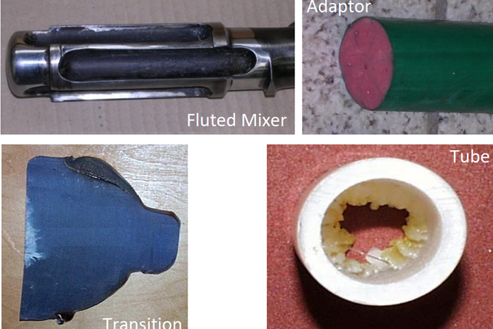
FIG 1 Common problems in medical tubing extrusion: Degradation in an oversized fluted mixer; polymer stagnation along the wall of an adapter; degradation in the transition from the breaker plate to the adapter; and periodic discharge of degraded material from the inner surface of a tube die.
Typical problems in medical tube extrusion include polymer degradation, long product-development time, sensitivity or instability of the process, die design, and high scrap rates (see Fig. 1). These problems can be reduced or eliminated by properly engineering and optimizing the equipment and process conditions. What causes degradation, for instance? Answers would include low shear stress, long residence time, operator errors, excessive temperature, very high shear stress.
We were recently engaged by a processor that was using an 18- and a 25-mm extruder with L/D ratios of 24:1 and 30:1, respectively, for a medical tubing project. A die was made for the project, but trials indicated degradation of material, polymer stagnation, burns at transitions, marks on the extruded product, and tolerance variations. We used VEL (Virtual Extrusion Laboratory from Compuplast) simulation software to reduce the trial and error that would otherwise be involved in finding the source(s) of these problems and the resulting waste in time, money and materials.
Shear Rate and Shear Stress
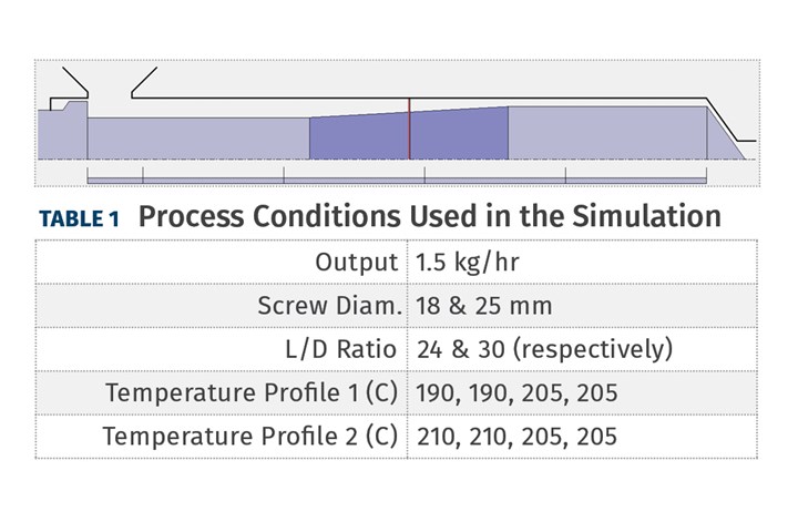
Table 1 (above) shows the typical barrel heater temperature settings this processor was using. The following equation describes the relationship between the shear stress, shear viscosity, and shear rate:
τ = η × γ
Where:
τ = Shear Stress
η = Shear Viscosity
ϒ = Shear Rate
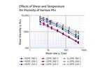
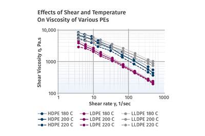
Figure 2 shows typical shear-viscosity versus shear-rate data for TPU at five temperatures. This type of material data is required for proper engineering of the extrusion equipment. The values in the graph emphasize how the viscosity varies with temperature and shear rate.
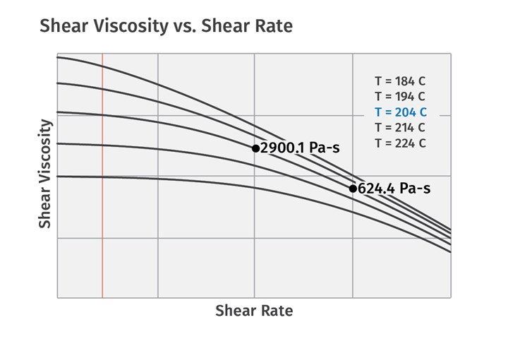
FIG 2 Typical shear-viscosity vs. shear-rate data for TPU at five temperatures (T). The values in the graph emphasize how the viscosity varies with temperature and shear rate.
Shear thinning is a common behavior for polymers in general, and it is the main material characteristic that determines how a material will flow through a die. The shear stress that the material exerts on the metal wall (wall shear stress) determines whether the system will be “self-cleaning” or will promote degradation. Without sufficient wall shear stress, a layer of essentially stagnant material will be formed and, over time, will degrade.
Shear thinning is a common behavior for polymers in general, and it is the main material characteristic that determines how a material will flow through a die.
Maintaining adequate wall shear stress helps avoid this type of degradation and allows the equipment to operate for a longer time before it needs to be disassembled and cleaned. What is a sufficiently high shear stress? Well, it is not known for certain and may depend on the type of polymer, but here are some design values that have been used successfully.
- LDPE: 30 kPa
- PVC: 35 kPa
- HDPE: 30 kPa
- LLDPE: 30 kPa
- EVOH: 50 kPa
(Shear rate should be more than 8 1/s)
Note that these are “design values” and have some safety factor included to allow for variations in production rate. The actual critical values are probably 50 to 70% of the above reported figures.
Extruder Simulation
Table 1 shows a sketch of an extruder screw profile (flights not shown) along with typical process conditions. In this case, the required output is 1.5 kg/hr.
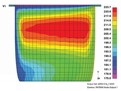
That screw geometry and process conditions were selected to simulate the performance of an 18- mm screw. Figures 3 and 4 show the shear rate and shear stress along the screw, respectively.
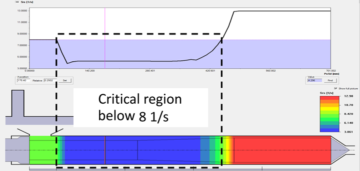
FIG 3 Shear-rate profile along the screw. The blue-shaded area in the graph shows the region below a “critical value,” which should be avoided. The critical wall shear rate is 8 1/s and a large portion of the screw surface is below this value.
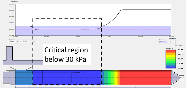
FIG 4 Shear-stress profile along the screw. As the blue-
shaded area reveals, a large region of the screw surface has a wall shear stress below the “critical value” of 30 kPa.
The blue shaded area in the graphs shows the region below a “critical value,” which should be avoided. The critical wall shear rate is 8 1/s and a large portion of the screw surface is below this value (Fig. 3). Figure 4 is the corresponding graph of the wall shear stress and shows that a large region of the screw surface has a wall shear stress below 30 kPa. Such “critical values” have been determined empirically by a large number of flow fields and correlating observations of degraded materials on walls to shear rate and shear stress.
Figure 5 shows a screw surface with a layer of degraded material caused by low shear rate and shear stress. Degraded material on the screw can appear as black specks in the product, affecting product quality and aesthetics.
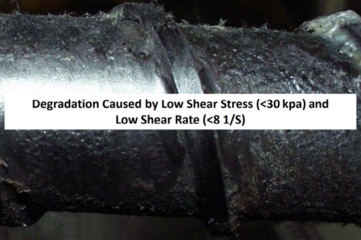
Table 2 summarizes the minimum shear rate and shear stress on the existing 18- and 25-mm diam. screws, at various process conditions for a throughput of 1.5 kg/hr.
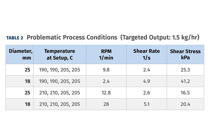
All of the conditions the processor proposed resulted in very low wall shear rates and some also had low wall shear stresses. The conclusion was that the processor’s extruders were too large for such a low-output extrusion project.
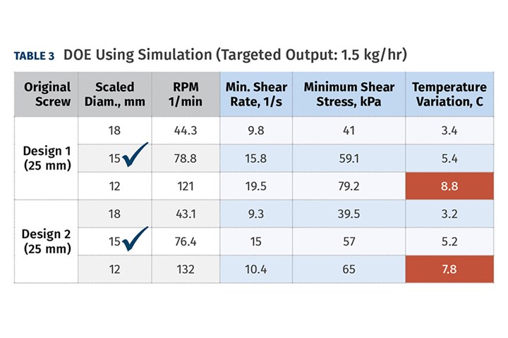
Table 3 shows a simulated DOE in which different designs were evaluated for adequate shear rate and shear stress at the required output. The predicted temperature variation is also shown.
It is often difficult to realize that there is degraded material forming in the die if it occurs on the inner surface
Results of simulations using the VEL software in Table 3 revealed that the 15-mm design generated sufficient wall shear rate and wall shear stress, while also providing acceptable melt-temperature variation. A new, smaller extruder with the optimized screw was installed, and the processor reported significant reduction in scrap during startup and complete elimination of black specks in the product.
In this project, it was found that the equipment available to the manufacturer was too large for the relatively low output that was required for this project. Consequently, the polymer was degrading on the screw surface. Ultimately, simulations identified a smaller extruder, with a screw optimized for the low rate, more applicable for the project.
It was also determined through simulations that the die was not optimized, as it also had many regions of low shear rate and low shear stress on the metal surface, where the polymer would ultimately degrade. It is often difficult to realize that there is degraded material forming in the die if it occurs on the inner surface. Follow-up analyses that helped the manufacturer design a die better suited for the project are planned for a follow-up publication.
About the Author: Dr. Ben Chouchaoui is a technical consultant for Windsor Industrial Development Laboratory Inc., Windsor, Ont., where he has worked since 2009. In his career, he has boosted technical capabilities of employers in FEA/CAE and CFD/CAM; established laboratory and simulation tools for demanding functional systems; correlated numerical calculations to processing and durability tests of products; supervised engineers; managed government-funded research; developed and maintained accounts (clients); and trained new engineers and R&D personnel in FEA and CFD. Contact: 226-340-7212; bencho@windsorlabs.ca.
Related Content
Part 2 Medical Tubing: Use Simulation to Troubleshoot, Optimize Processing & Dies
Simulation can determine whether a die has regions of low shear rate and shear stress on the metal surface where the polymer would ultimately degrade, and can help processors design dies better suited for their projects.
Read MoreTight-Tolerance Molder Dips Toe in Extrusion Waters
Midwest Precision Molding brings extrusion capacity in-house to assist a customer that was having a sourcing issue with its existing overseas suppliers.
Read MoreCorrugated Tube Crossheads
Multiport spiral-flow design is said to provide a balanced compound distribution with no weld lines to the corrugator.
Read MoreHow to Select the Right Tooling for Pipe Extrusion
In pipe extrusion, selecting or building a complementary set of tooling often poses challenges due to a range of qualitative factors. Here’s some guidance to help you out.
Read MoreRead Next
Four Keys to Consistent Tubing
Because of their use in critical applications, processors of medical tubing have little or no room for error.
Read MoreUnderstanding Viscosity in Extrusion
Both the power-law coefficient and the consistency index must be considered to calculate viscosity.
Read MoreThe Role of Screw Design In Efficient Extrusion Of Medical Devices
For extruders of medical tubing, screw design plays a key role in maintaining dimensional control, physical properties, and more.
Read More

