
Do You Still Get Stubborn Surface Defects, Even With Sequential Valve Gating?
Hot Runners
Sequential valve gating either eliminates or greatly reduces the flow-front collisions, and resulting knit lines, between a set of nozzles. However, there are still applications using sequential molding where a “ghost mark” or marks occurs on the part between a set or pair of nozzles and/or near the gate itself.
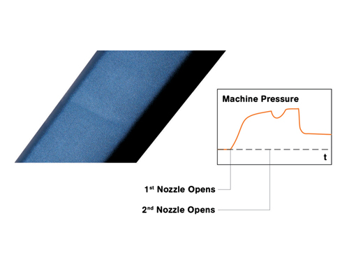
Fig. 1: “Shadow” on part indicates flow hesitation mark caused by a temporary dip in pressure when the second valve-gate nozzle opens.
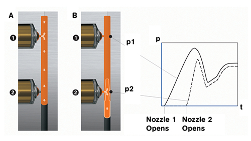
Fig. 2: The initial “blast” of melt entering the cavity from opening the second VG nozzle contributes to an immediate rise in pressure, followed quickly by a dip in pressure, which can lead to flow hesitation.
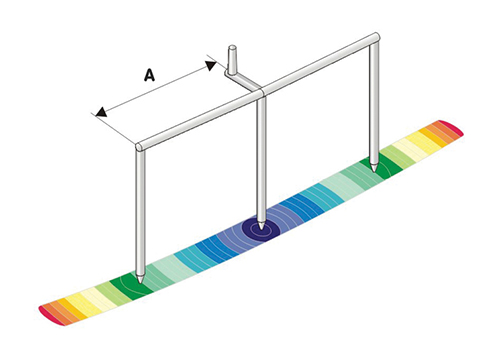
Fig. 3: In a case study of molding auto interior trim parts, this flow simulation shows the change in flow velocity caused by opening the outer pair of VG nozzles once the flow front from the center nozzle reached the outer nozzles. The arc in the flow isochrones (green) shows increased flow rate from a sudden “blast” of material from the secondary nozzles.
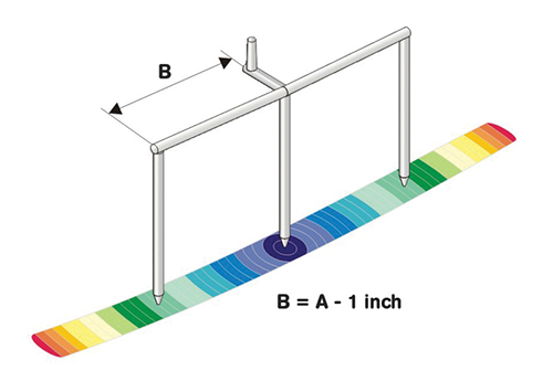
Fig. 4: Flow simulation of Solution #1 shows that moving the outer VG nozzles closer to the center of the part, together with slower opening of the secondary valve pins, produced uniform flow rates before and after the flow front reached the outer VG nozzles.
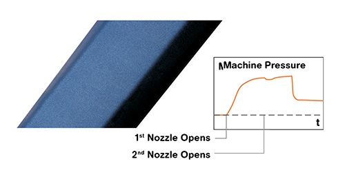
Fig. 5: Solution #2 achieved a result similar to Solution #1 by not moving the outer nozzles and instead using velocity control for opening the outer valve pins to introduce melt at a “softer” rate rather than a hard “blast.” The result was less pressure drop when the secondary valve pins opened and greatly reduced hesitation marks.

Using hot-runner valve gates to deliver melt sequentially to a mold cavity or cavities has been in practice for decades. This technique involves having multiple nozzles for a single part or set of parts and keeping all valve-gate (VG) pins closed while opening a single or selected group of nozzles until the melt passes the second nozzle or group of nozzles. The next nozzle or set of nozzles is then opened, thereby moving the knit line to the end of the part or to a more suitable location on the part.
Sequential valve gating either eliminates or greatly reduces the flow-front collisions, and resulting knit lines, between a set of nozzles. However, there are still applications using sequential molding where a “ghost mark” or marks occurs on the part between a set or pair of nozzles and/or near the gate itself. To explain the cause of this defect and the solution, case studies were performed on two different two-cavity VG systems, each with three drops per part. The parts are used for interior automotive trim.


The problem experienced by the molder was unexpected flow marks on the surface of the part (the “shadow” visible on the part in Fig. 1) that the molder was unable to reduce. Filling of each part started with opening one VG nozzle per part once an Injection Forward signal was received. The second VG nozzle was opened when a setpoint for screw stroke (melt volume) was achieved, as was the third nozzle. Despite numerous processing methods and sequence-delay options, two undesirable marks on the part resembling knit lines were visible.
These marks or “ghosting” can be better defined as flow hesitation marks. The material flow hesitation is created by the very sudden change in pressures as the melt is introduced into the cavity at an initial high rate of velocity as the sequence of VG nozzles actuates (Fig. 2). The material from the second VG “blasts” into the cavity, backfilling and jetting within the part with the quick opening of the VG pin. That quick initial pressure rise then dissipates, causing the “hesitation.” As shown in the graphs in both Figs. 1 and 2, the injection pressure dips immediately after the second pin opens because the machine pressure is now distributed over two or more open valve gates instead of just one.
Mold-filling simulation, together with past experience in molding similar parts, can allow one to to predict the possibility of such a problem, though not necessarily how bad the result might be. With such warning, appropriate actions can be applied before the mold and hot runner are designed and built.
Solution #1: MOVE THE NOZZLES
Figure 3 is a filling simulation displaying material flow paths in time increments called isochrones. The part is sequentially valve gated, starting with the center gate. After the material flows past the second two nozzles, they are opened simultaneously. The suggested nozzle spacing or pitch was supplied by the molder. Please note the arc in the isochrones directly after the second nozzles. This shape suggests an introduction of material at an initially higher velocity than the melt from the first nozzle, which can result in flow hesitation.
Figure 4 is the same tooling setup, except that Incoe had suggested moving the two outside gates closer to the center of the part. The simulation now shows the isochrones as straight lines, indicating that the material is introduced into the cavity at relatively the same rate as the melt passing by gates 2 and 3.
The conclusion was to use the closer nozzle spacing in Fig. 4, as well as slowing the VG pin retraction. The result was acceptable to the customer, molder, and moldmaker.
SOLUTION #2: CHANGE PIN ACTUATION SPEED
The second case study was to eliminate the part surface defect seen in Fig. 1 and achieve the result in Fig. 5. In this case, moving the positions of the VG nozzles as in Fig. 4, or possibly even adding more drops, were not viable options. Instead, the existing hot-runner system had to be replaced. The replacement system included a low-cost, simple-to-use technology that allows the processor to vary the VG pin velocity from the fully closed position to the open position. This technique introduces the melt into the cavity at a “softer” rate, lowering the pressure drop (compare Fig. 5 to Fig. 1) and reducing the change in material velocity flowing into the cavity when compared with the initial “blast” of material without this technology. The end result was equally acceptable to Solution #1.
The sequential VG technologies discussed here can reduce a variety of aesthetic defects besides the flow-hesitation marks discussed here, such as wrinkles in overmolded material.


Related Content

How to Select the Right Tool Steel for Mold Cavities
With cavity steel or alloy selection there are many variables that can dictate the best option.
Read More
How to Mount an Injection Mold
Five industry pros with more than 200 years of combined molding experience provide step-by-step best practices on mounting a mold in a horizontal injection molding machine.
Read More
How to Optimize Pack & Hold Times for Hot-Runner & Valve-Gated Molds
Applying a scientific method to what is typically a trial-and-error process. Part 2 of 2.
Read More
Where and How to Vent Injection Molds: Part 3
Questioning several “rules of thumb” about venting injection molds.
Read MoreRead Next

How Polymer Melts in Single-Screw Extruders
Understanding how polymer melts in a single-screw extruder could help you optimize your screw design to eliminate defect-causing solid polymer fragments.
Read More
Why (and What) You Need to Dry
Other than polyolefins, almost every other polymer exhibits some level of polarity and therefore can absorb a certain amount of moisture from the atmosphere. Here’s a look at some of these materials, and what needs to be done to dry them.
Read More