Secrets of Success in Micro Molding
Medical-device, electronics, and biopharmaceutical manufacturers need new micro-molded products to create tinier, less invasive, and/or space-saving micro devices.
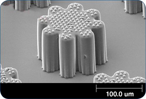
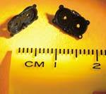
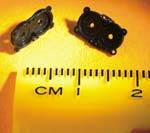
Medical-device, electronics, and biopharmaceutical manufacturers need new micro-molded products to create tinier, less invasive, and/or space-saving micro devices. Micro-molded components can be as small as dust specks and/or have features that small. State-of-the-art micro parts can have molded features such as dimples around 3 microns in depth and diameter—more than 80 million of them across a surface the size of a microscope slide. (see Fig. 1 ). The tiniest parts in an assembly are the ones most likely to be a challenge and are also usually the enabling component of the entire device’s form, fit, and function. Similarly, micro tooling created by micro machining is critical to these parts ever making it to validation.
Many new advances in micro-machining technology are enabling design and manufacturing of micro molds, which then enable micro injection molding in thermoplastic, silicone, and metal powder. This is leading to worldwide advances in less invasive medical and pharmaceutical micro devices. This article provides a view of the challenges and solutions to many of the major elements of success to molding micro devices and assemblies.
THE CHALLENGE
Most micro products start with some level of extreme challenge. It is rare that they are manufacturable as initially designed or napkin-sketched; often they are scaled-down versions of something similar on the market, just several magnitudes smaller and/or requiring an experimental material to accommodate a drug-releasing agent or other special characteristic.
Micro assemblies are getting more complex due to their need to fit into tiny and delicate arteries, pumps, catheters, or endoscopes with actual working micro components inside. These often have challenging geometry because they were once designed as two or more components but have been cost-reduced to one so that they do not have to be assembled under a microscope. In many cases, such as with powder inhalers, they were once more than 20 micro components redesigned to fewer than five parts.
These devices may require pharmaceutical drugs directly compounded with or added to polymers, metals, or membranes and have working gears, levers, and drive mechanisms to make the device function repeatedly and with robust longevity. With these functions in mind, and the fact that these devices may be directly implanted into the body, it is important that they be developed in a robust way and are well tested for form, fit, and function.
MICRO-FLOW ANALYSIS
Because micro molds and prototype parts can be costly in their development cycle, micro mold-flow analysis provides insurance that a particular design will fill with the intended material. An all too common assumption when comparing parts made by conventional molding to micro molding is that micro parts can be filled with the same software and same modeling methods.
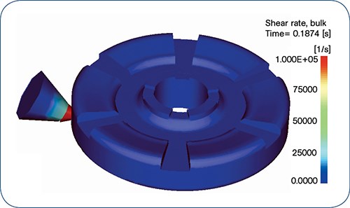
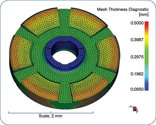
For example, flow analysis involving a typical 0.020-in. (500-micron) gate is very different from modeling flow through a 0.003-in. (75-micron) equivalent gate. The difference is that the micro part with the micro gate sees much more shear-induced heating (Fig. 2) in pushing through that small orifice. As a result, the solid-model mesh (Fig. 3) must have extremely high resolution to determine what is happening in the gate and thin-wall areas. The mesh of a solid model used in a mold-flow simulation requires single-digit microns (0.0001-0.0002 in.) while a mesh of tens of microns (0.0005-0.001 in.) is required in the part.
Another important factor in a mold filling or cooling simulation is direct practical knowledge of injection molding and moldmaking. The most talented computer jockey in the world would struggle without knowledge of plastics engineering, micro mold design, gate location and sizing, and runner and sprue geometry.
Process-specific and material-specific knowledge are also essential. The gates of micro-molded components will have to be properly sized so as not to place undue heat stress on the material entering the cavity. For heat-sensitive materials such as bioresorbable and biopharmaceutical polymers, the residence time in the injection barrel, nozzle, and hot runner must be understood in relation to additional heat that may be imparted to the material during injection.
At times, the material drives the process choice, and at other times the process drives the material choice. Some common materials for micro molding are PEEK, PLA, PGA, LSR, polyethylene, polypropylene, polycarbonate, LCP, PMMA, cyclic olefin copolymers (COCs), and stainless steel (metal injection molding).
TOOLING
When the design and material are nailed down to the point of spending capital to test the components, it’s time for a micro mold to be made. Whether the material is thermoplastic, silicone, or metal powder, the tooling is the most critical component to success. Micro machining is the enabling technology for creating hair-sized core pins and micro channels and cavities.
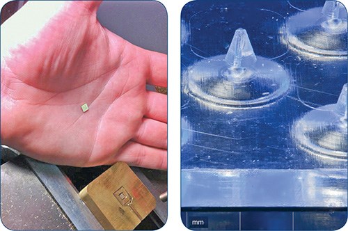
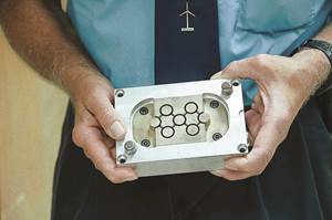
Because the parts and molds are so small (Fig. 4), the tolerances get smaller and the tooling must still be made to 25% of part tolerance to provide a good processing window. With tolerances of ±0.0005 in. (±0.01mm), the steel tolerances must be ±0.0001 in. (±0.003mm) to achieve a good window. There are not many tooling suppliers in the world that will sign up for these tolerances, for two main reasons:
1. They can’t measure ±0.0001 in. (±0.003mm) and therefore cannot validate.
2. They lack the equipment or skill set to achieve these tolerances.
•Runner/sprue: The runner and/or sprue (if one exists), can be our friend or foe in micro assembly. We could use it as a handle to hold onto a part in automated assembly operations or add special locating “jogs” in the runner to aid in positioning the piece in an assembly nest.
•Parting lines: Parting lines on the order of 0.0002-0.0003 in. (10 microns) are significant in relation to the size of micro parts. Those 10 microns can easily make or break your assembly and must be considered when the part will be assembled to other parts, as it can prevent proper fit if the part is not guided or moved through the assembly process properly.
•Draft: More is better but can be as small as 0.2° of taper. This taper, inside or outside a molded part, can be cumbersome to deal with. Having your micro part “ride” on a taper will provide an arbitrary or irregular surface that can position it improperly for assembly to other parts. Ways around this are to eliminate draft on a small portion of the part being positioned, draft the assembly station/fixture with the matching draft angle, or add a drafted feature to the part or runner that can be used and removed later on.
•Gate location: What is true of any injection molded part is all the more so in micro molding: It is critical to choose a gate location that will create uniform flow in the cavity. Without that, the part may not fill and could result in damage to delicate pins and cavities.
•Gate vestige: Most micro molded parts use an edge gate. If so, they need to be degated properly to avoid issues with small “picks” of material causing damage to an artery (in implanted devices) or causing issues with automation and assembly. These small picks can be addressed in the mold design by placing a dimple in the wall thickness (if the walls are thick enough) so the vestige will “sit” below the surface of a guide or a mating component in the assembly.
•Surface finish: Often overlooked, the surface finish of a molded part is important in “riding” or “guiding” features into other features during assembly. Some surface finishes are best achieved with vapor honing or roughening the surface to provide improved surface area for bonding, for example. Smooth surfaces can cause problems in ejection from the mold and a compromise may be required.
INJECTION MOLDING PROCESS
If tooling is the enabler, then there’s the micro injection molding process to get you the remaining 10-15% to the finish line. With micro molded parts and features in the single-digit micron range, there are several challenges to achieving good tool replication in the molded part. It is one thing to make nice sharp corners and cavities in steel (less than 1 micron radii) but quite another to fill those tiny spaces with polymer. Proper venting is required, sometimes with extremely thin laminates (puzzle pieces of steel) to achieve proper degassing and filling of sharp corners.
Typical injection pressures in micro molded parts are upwards of 30,000 to 50,000 psi, which requires a delicate balancing act to fill at adequate pressure without displacing tiny, hair-thin core pins. Dust-speck-size parts with extremely thin walls (0.001-0.0015 in.) require extreme cavity-to-core alignment across parting lines.
This allows balanced flow throughout the tool without freezing off. If the polymer freezes off in a non-fill condition, or if the part fills more on one side than another, it is likely that micro core-pin damage will occur. This challenge is overcome with fast fill at short injection times (typically < 0.1 sec) and high pressures. With these two variables, it is clear that the tool must be robust and highly precise to meet these challenges during fill.
There are around a dozen manufacturers of specialized injection machines tailored for micro molding. The range of choices has at least tripled since 2005. Micro molding machines must be able to inject very small shots and keep the residence time in the barrel to a minimum. This is especially important for bioresorbable polymers (PLA, PGA), which are highly shear and heat sensitive. Specialized screws, nozzles, and auxiliary equipment are also needed to provide the level of precision of filling, handling, degating, measuring, and assembling these tiny devices.
ASSEMBLY & HANDLING
The best way to handle microscopic parts is to not handle them at all. Combining geometries into the least number of parts for a micro assembly is design work well worth the effort because picking them up, registering them in nests, and joining them to other parts of like or unlike materials can be much more costly than spending the time upfront in the design stage.
•Two-shot micro molding/overmolding: Injecting two different materials into a mold at two different locations or in the same location with a rotating mold enables one setup of combination geometry and materials. For example, if a pump piston requires a seal or silicone gasket, it is easier to overmold a gasket into an o-ring groove in the same mold as the piston than it is to bowl-feed an o-ring onto a precision tracking mechanism, grip the o-ring with some scissor grippers, and place it over the piston. The o-ring would be subjected to stretching and shape distortion with the scissors, bowl feeding, and riding on a track of an assembly system.
•Laser welding: If 3D geometry can’t be combined through overmolding, and material strength allows for it, laser welding is a good method for joining micro components. Careful control of laser energy and power densities also can be used to selectively clean and strip materials such as wires quickly and non-destructively.
Laser beam sizes in the sub-micron and lower range and pinpoint accuracy of multiple laser welds are possible using a nano-positioning table or a multi-axis robot station mounted on a rotary table or shuttle system. Laser welding can use existing wall thickness or an extra “tab” designed into the component being welded, or a small amount of similar material can be introduced using wires, as is done in soldering electrical components.
•Ultrasonic welding: Ultrasonic welding is also effective to join thermoplastics as well as compatible metals. Specialized low-energy boosters and ultrasonic horns are required for micro components as the amount of energy required for a strong weld is extremely low.
•Spin welding: This is usually not a good option for micro parts, due to the very thin walls; however, a very tiny (100-200 μ) weld bead is sometimes possible.
•Solvent bonding: This is often used as a quick, low-capital-investment method for joining micro components. “Quick-and-dirty” fixtures can easily test the feasibility of bonding dissimilar materials using micro and nano pipettes to distribute the tiny amounts of solvents. Appropriate solvents must be compatible with the materials being bonded, especially if the assembly is to be used as an implant. Ramping up a high-volume assembly process with solvent bonding can be headache-ridden, as the method is not easily automated and repeatable, and it’s messy and difficult to validate on a high- volume scale.
•Staking: Micro staking is a very inexpensive method to join polymer and metal components. In battery cans, for example, crimping or staking is a very common practice to generate good seals for preventing caustic fluids from escaping the battery vessel. Inexpensive progressive stamping dies enable a moderately fast method for staking both polymers and metals to one another using a pressurized “folding” of one material into another. Material lot variations can be a drawback of this method.
TESTING
An important aspect of automated micro assembly systems is testing, such as for electrical conductivity, leakage or pressure decay, and burst strength. Some are destructive and some are nondestructive. The best way to determine if your final assembly or sub-assembly will function properly is to keep your process in control for each component that makes up the assembly.
Statistical validation of each component and revalidation of the assembly will prevent costly testing and inspection in an automated cell later; but sometimes they may be unavoidable, especially with implantable and critical drug-delivery applications.
Automatic, inline testing can be performed in cycles shorter than 2 sec for high-volume applications. It’s not unreasonable to test sub-assemblies both on their own and within a final assembly on the same piece of automation. The main reason to test sub-assemblies first is the cost of components that will be added to make the final assembly. For example, a catheter with two plastic components and a wire sub-assembled and leak tested will be far less costly to scrap (using a shuttle off to the side for that particular station) than it would be to test the final catheter with five plastic components, two metal ones, and a handle. Sub-assembly testing can be statistically reduced once the automation process and your incoming micro components are in control—both of which usually happen during validation and clinical trials as product volume ramps up.
Some tests may take longer than is affordable in a high-volume automated cell, and parts may have to be selected at statistical intervals and shuttled off onto a side track. For example, a pressure-decay test may take 3 to 4 sec. If the test is nondestructive, parts can be shuttled back into the production line.
INSPECTION METROLOGY
We’ve all heard that “you can’t make it if you can’t measure it.” In medical and pharmaceutical devices, where critical components can be a matter of life or death, this also means “you can’t make it if you can’t validate it.” Micro metrology should be avoidable if parts are manufactured consistently and validated. But any time we are asked, “Can you say without hesitation that this assembly will work in the application 100% of the time?” the answer must be in the negative until all components have run with several different lots of material, at different times of the year, at several different humidity and temperature levels, etc. Therefore inspection is inevitable at least until we can statistically prove all of the above over a long period of time. For critical implants, inspection is a certainty for the life of program.
There are many viewpoints when it comes to inspecting micro components and assemblies. Some can be inspected with high-resolution cameras just to verify a feature or surface finish. Some require 3D laser scanning to verify a number of critical dimensions. Some others require high-speed video cameras to show powder or picoliter liquid dispensing has been achieved to the correct dosage.
Inspection is often overlooked and becomes an after-thought. But with micro components and assemblies, it is critical to consider during the prototyping stage, even to determine if the Cpk of the device and the stack-up tolerances of the components will fit within the functional range of the final assembly.
Related Content
Optimizing Pack & Hold Times for Hot-Runner & Valve-Gated Molds
Using scientific procedures will help you put an end to all that time-consuming trial and error. Part 1 of 2.
Read MoreBack to Basics on Mold Venting (Part 2: Shape, Dimensions, Details)
Here’s how to get the most out of your stationary mold vents.
Read MoreHow to Select the Right Tool Steel for Mold Cavities
With cavity steel or alloy selection there are many variables that can dictate the best option.
Read MoreThree Key Decisions for an Optimal Ejection System
When determining the best ejection option for a tool, molders must consider the ejector’s surface area, location and style.
Read MoreRead Next
Micromolding Sizing Up the Challenges
Molding multiple parts from one pellet's worth of plastic is a challenge that growing numbers of molders want to tackle. It is driving development of new technology in injection machines, tooling, parts handling, and inspection.
Read MoreMaking the Circular Economy a Reality
Driven by brand owner demands and new worldwide legislation, the entire supply chain is working toward the shift to circularity, with some evidence the circular economy has already begun.
Read MorePrecision Processing Requires Precision Equipment
Moretto offers plastics processors and micromolders for a broad suite of auxiliary solutions targeted specifically for precision processing.
Read More
