Know Your Options in Injection Machine Nozzles
Improvements in nozzle design in recent years overcome some of the limitations of previous filter, mixing, and shut-off nozzles.
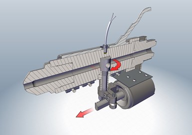
Externally Actuated Shut-Off Nozzles use hydraulic or pneumatic cylinders to actuate a shut-off mechanism. Shut-off mechanisms can use a variety of methods, including the rotational shut-off shown in this cutaway.
In today’s global manufacturing environment, molders are looking to optimize their injection molding processes in every way possible. Various types of machine nozzles can help accomplish that goal. Machine nozzles today can provide a variety of functions, including filtering, mixing, and shut-off of melt flow.
Minimizing the clogging of gates and/or hot runner tips due to foreign material or contamination in the melt stream with nozzle filters can readily improve uptime while also minimizing damage to gates and hot-runner tips. Molders using additives such as colorants at the molding press commonly employ mixing nozzles to enhance dispersion and mixing of additives, improving molded part quality while also reducing the volume and cost of additives. Finally, shut-off nozzles can minimize drool in molding operations where the press is frequently disengaged from the mold, such as in many two-shot molding applications.
MODULAR NOZZLE DESIGNS
Machine nozzles are designed to be easily threaded onto the injection molding barrel. This implies that the back end of each nozzle is customized to thread onto the specific machine barrel for which it is to be utilized. Thus, each nozzle tends to be utilized with one particular type and size of injection molding press.
Some machine nozzles are of single-piece construction, which may result in less expense initially. Other nozzles are of modular design and construction, which commonly offers separate components for the nozzle body, machine interface, and mold interface. Modular designs offer a number advantages, the primary one being the ability of a single nozzle body to interface with multiple injection barrels and multiple molds.
Modular nozzles have interchangeable components that can interface with multiple injection barrels and mold sprue bushings.
In a modular design, the interface with the injection barrel is separate from the nozzle body, permitting the nozzle body to be run on multiple presses with different barrel thread specifications. Separate interfaces, each with the appropriate thread specifications for the injection molding barrel that it is used on, can be attached to specific injection presses, each with a common interface to the nozzle body. In this manner, the nozzle body may then be easily fitted to all of the various injection molding barrels used in a molding facility.
The front end of the machine nozzle is also customized to ensure that it matches and properly interfaces with sprue-bushing radii of the molds with which it will be used. A modular machine nozzle design includes a modular tip that can be easily exchanged, allowing the molder to have multiple tips to allow one nozzle to properly interface with multiple molds, each with different sprue-bushing specifications.
SCREEN-PACK NOZZLE FILTERS
Nozzle filters capture contaminants in the melt stream to prevent such particles from entering the mold and the molded parts. Nozzle filters come in a variety of styles. The most common style is known as a screen pack. It consists of a metal disk perforated by a number of small holes, which is inserted along the inner diameter of the flow channel of the machine nozzle. As the melt passes through the flow channel of the nozzle, it encounters the metal disk and is squeezed through the small-diameter holes. Particles or contaminants larger than the holes are captured and prevented from traveling into the mold.
Advantages of a screen pack are its simple design and low cost. It is also relatively easy to size the diameters of the holes in the metal disk. There are multiple disadvantages to screen packs, as well. The first and foremost disadvantage is that to ensure the structural integrity of the metal disk against the injection molding pressure, the area of the solid metal will be greater than the aggregate area of the small-diameter holes contained within the metal disk. Thus, by its very design, the screen pack reduces the flow-channel area by at least half. This results in a noticeable and significant pressure drop as the melt traverses through the screen pack. This pressure drop is large enough to impact the processing window, and thus is unacceptable to many molders. Most molders will not utilize screen packs or will limit their utilization to injection molding presses and/or molds where this type of pressure drop is deemed absolutely necessary.
A second disadvantage of screen packs is that each particle or contaminant that is captured effectively blocks one of the small-diameter holes of the screen pack. Once a hole is blocked the effective flow area of the melt is reduced further, which results in an additional increase in the pressure drop.
As more contaminants are captured, the pressure drop continues to rise even further. Given the relatively small effective flow area of the screen pack to start with, each further reduction in flow area has a noticeable further increase in pressure drop. At some point, as enough contaminant is captured, the pressure drop will reach a level that prevents acceptable molding. At this point, the screen pack must be cleaned, which exposes a third disadvantage of this nozzle design.
To clean the screen pack, the machine nozzle must be cooled down and disassembled so that the screen pack can be removed from the nozzle filter. The screen pack must then be cleaned or replaced. A clean screen pack is inserted into the nozzle filter, and the machine nozzle is then reassembled.
Once reassembled, the machine nozzle can then be brought back up to the proper operating temperature and molding may recommence. The entire process — from shutdown of molding, through cooling down, disassembly, cleaning, reassembly, and heating up — may easily take a couple of hours or more, depending upon the size of the machine nozzle.
The first disadvantage of the screen pack (high pressure drop), coupled with its other disadvantages (quickly increasing pressure drop and time-consuming cleaning), have limited its use to applications where the cost of contaminants in the melt stream outweighs these inherent design disadvantages.
GAP-FILTER MACHINE NOZZLES
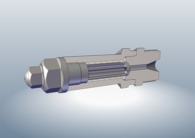
Here is a type of gap filter nozzle that filters melt over thin ribs between axial melt channels. It offers lower pressure drop and longer time between cleanings than a screen-pack filter nozzle.
An alternative design of melt filter is the gap filter, also sometimes referred to as an edge filter. The gap filter turns the filtering of the melt 90°, which permits a much larger flow area for filtering. This larger flow area results in significantly less pressure drop, the primary advantage of the gap filter relative to the screen pack.
The gap filter is cylindrical in shape. The outer diameter is precisely machined to allow it to slide into the bore of the inner diameter of the machine nozzle body with minimal clearance. Along the outer diameter of the gap filter, an even number of channels is machined, creating multiple parallel, lengthwise melt-flow channels along the outer diameter of the gap filter.
The machined groove flow channels are spaced close to each other with only a thin wall of steel separating each. The thin walls of steel are the side walls of the flow channels. When the gap filter is slid into the bore of the inner diameter of the machine nozzle, the inner diameter of the nozzle creates a lid on top of the machined groove, fully enclosing the melt-flow channels.
The machined groove melt channels stop short of either end of the gap filter. On one side of the filter, holes are then drilled into every other machined groove, to allow the melt to flow into every other melt-channel groove from the injection barrel side of the nozzle. On the mold side of the cylinder, holes are drilled into the alternating melt-channel grooves, which permit melt to flow out of every other machined groove and into the mold.
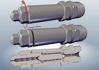
Special purgeable version of gap filter nozzle. To purge, thread the nozzle tip forward about 5 mm, and then purge material in the barrel. Contaminants trapped in the filter will be pushed out through the nozzle tip via the bypass channel.
At this point the melt can flow from the injection barrel into the gap filter through half of the machined-groove melt channels. The melt travels to the end of the machined-groove melt channels where they are then trapped within the gap filter with no way to access the machined groove melt channels that exit the filter into the mold.
The walls or thin ribs of steel on either end of the machined grooves are machined down slightly. This creates a predefined “gap” between the ribs or thin walls of steel that separate each of the machined groove melt channels and the inner bore of the machine nozzle. These gaps allow melt to roll over the thin walls that separate adjoining machined groove melt channels. Thus the melt may continue to traverse from one grooved flow channel into adjacent grooved channels by flowing over the tops of the ribs. The size of the machined gaps determines how easily the melt can flow from one melt channel to an adjacent flow channel and also sets the size of particle or contaminant that will be captured in the gaps between the tops of the ribs and the inner diameter of the machine nozzle.
The gap filter nozzle solves the problems of high pressure drop and frequent filter cleaning experienced with screen-pack filter nozzles.
The aggregate flow area of the multiple gaps created between the tops of the ribs and the inner diameter of the nozzle filter is significantly larger than the aggregate flow area of screen packs, which results in easier flow of the melt and significantly less pressure drop. Another advantage of this design is that as contaminant is captured, it plugs a much smaller percentage of the flow channel. Thus, considerably more contaminant may be captured in a gap filter before any noticeable increase in pressure drop occurs. With a gap filter, it is quite common that even after running for some time and capturing a fair amount of contaminant, the gap filter may still have a lower pressure drop than a clean screen pack. The lower pressure drop allows molders to filter melt with a minimal impact on the processing window.
A final note on the gap-filter nozzle is that there is a design available that permits purging of the contaminant without having to remove the filter from the nozzle. With the purgeable nozzle filter, contaminant can be purged without having to disassemble the nozzle. This design provides for minimum downtime during cleaning, as the nozzle filter may be purged within a few minutes between shots, providing maximum uptime on the processing floor.
MIXING NOZZLES
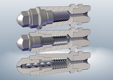
Triple-Action Mixing Nozzle uses intricate geometry to ensure that the melt is thoroughly mixed, using three alternating rotations to gently fold the melt onto itself three times. It also provides a tuneable degree of melt filtration.
Mixing nozzles help ensure a consistent and uniform dispersion of additives, such as colorants, and maximize the effectiveness of such additives. Mixing nozzles also help ensure a more consistent and homogeneous melt overall, including temperature dispersion. Some mixing nozzles utilize changes in flow-channel volumes to create alternating areas of higher and lower pressure as the melt travels through the nozzle. Some mixing nozzles may introduce unacceptable levels of shear or stress to the melt. Additional shear and/or stress can be especially problematic for sensitive materials such as PET.
The “triple-action” mixing nozzle folds the melt onto itself, ensuring gentle yet through mixing of the melt. As the melt enters the nozzle it is directed to the outermost diameter, where clockwise spiral threads begin rotating the melt. Slotted openings on the inner diameter of the spiral flow channel then move the material inward into a second set of counterclockwise spiral flow channels, folding the thermoplastic melt onto itself once again as it begins rotating in the opposite direction.
Small-diameter holes on the inside of these flow channels allow the melt to progress another level inward, where it encounters a final clockwise spiral flow path that folds the material onto itself a third time in the opposite direction.
Mixing nozzles can be designed to avoid over-shearing sensitive melts while providing good temperature uniformity and additive distribution.
This triple-action mixing ensures a gentle yet thorough mixing of the melt. The slots and small-diameter holes that the melt passes through as it progresses inward along the nozzle provide the added benefit of filtering the resin as it progresses through the nozzle. The size of the filter can be customized to the molder’s specifications.
Given the complex geometry of the flow path that the melt flows as it traverses the triple-action mixing nozzle, changing colors may take more shots than is desirable. A simple solution for molders doing frequent color changes while utilizing the triple-action mixing nozzle is to have two mixing nozzles available. When changing colors, the molder simply swaps nozzles. The mixing nozzle that was pulled from the machine may then be cleaned and prepped for the next color change. Cleaning between color changes has the added advantage of cleaning out any contaminants that have been captured by the mixing nozzle.
The size of filtration and gentle mixing action of the triple-action nozzle minimize the pressure drop and amount of shear that the melt sees as it traverses through the nozzle. That makes the triple-action mixing nozzle a good candidate for applications using shear-sensitive thermoplastics, including PET, with color concentrate and/or other additives.
SHUT-OFF NOZZLES
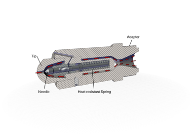
Automatic shut-off nozzles use a high-quality, heat resistant spring to provide a simple, effective shut-off mechanism that requires no operator set-up or intervention.
In some molding applications, such as some multi-shot molding jobs, it is necessary for the machine nozzle to back away from the mold with each shot. It is desirable to minimize the drool from the nozzle in such applications.
There are a wide variety of designs to shut off the melt, including shut-off pins or needles, ball-valve shut-offs, blade shut-offs, etc. There are also a variety of methods for actuating the shut-off, including hydraulics, pneumatics, or springs. Shut-offs can be timed by electronics triggered by the injection molding press or by injection pressure itself.
To simplify the process and minimize the potential for error, which in some cases can lead to catastrophic failure, the shut-off operation should occur automatically in most applications. It is also desirable that the shut-off nozzle includes a built-in safety feature to ensure that the nozzle is not over-pressurized in situations where the press is idle with heats on for an extended period.
A spring-operated mechanism that is opened by injection pressure can accomplish this in a simple, straightforward, and reliable manner. Once the injection pressure reaches a predetermined level, the spring is compressed, allowing the melt to flow past the needle valve, which is held open as long as the injection pressure remains above the predetermined level. As soon as the injection pressure drops below that level, the spring moves the needle valve forward into the closed position, automatically shutting off the melt flow.
The spring needle shut-off design has the advantage of working automatically without intervention of operator, sensors, or external actuating devices. No hydraulic or pneumatic hook-ups or controllers are required. Thus, each and every time a mold is put into a press it is ready to run, without adjustments.
Being contained within the machine nozzle and surrounded by molten thermoplastic, it is important that the spring used in such applications be high quality, long lasting, and temperature resistant to ensure that the spring does not anneal over time at the melt temperature. To minimize the potential for the melt to foul the spring, it is imperative that all components of the shut-off nozzle be precision machined. The design may also include a means of diverting any melt that finds its way along the shut-off needle away from the spring.
Additionally, if the barrel is left unattended with heats on for an extended period of time, the spring needle shut-off design has the advantage of a built-in safety feature, in case the machine nozzle and/or injection barrel begin building pressure. With valves that are externally actuated, the valve remains closed, even as pressure builds. If the the valve is then opened with the melt at the elevated pressure, the melt may shoot out of the machine nozzle uncontrollably, creating a potentially unsafe situation.
Even worse, if the valve is not opened soon enough to release the pressure, the pressure may build to a catastrophic level, again resulting in a potentially dangerous situation with little or no warning.
With spring actuation, once the pressure builds to the predetermined level, either because the molding cycle has been deliberately halted, or because pressure is rising in an unattended injection barrel, the spring will automatically open the needle valve, releasing pressure before damage or catastrophe occurs.
This is one more example of how the design and engineering of machine nozzles has improved considerably in recent years. The problems of too much pressure drop in nozzle filters; excessive shear and/or stress in mixing nozzles; and the high cost and complicated set-up and operation of shut-off nozzles have been resolved through efficient and effective design and engineering. Molders with operations that may benefit from nozzle filtering, nozzle mixing, and nozzle shut-off may be well served by the technologies that are now available.
About the Author
Chuck Azzopardi
Chuck Azzopardi is president of HMM Solutions Inc., Salida, Colo., which offers sales and support for machine nozzles and mold components from Müller Mekaniska AB of Sweden. Prior to forming HMM, Azzopardi was project/staff engineer at Plastic Engineering & Technical Services (P.E.T.S.) for seven years; senior injection molding specialist at BASF for eight years, and a product manager and global business manager at DME Company for nine years. Contact: (719) 221-6444; nozzles@hmmsolutionsinc.com
Related Content
How to Optimize Pack & Hold Times for Hot-Runner & Valve-Gated Molds
Applying a scientific method to what is typically a trial-and-error process. Part 2 of 2.
Read MoreFive Quick Steps Toward Better Blending
Rising costs of resins and additives, along with higher demands for quality and use of regrind, place a premium on proficient blending. Here are some steps to get you there.
Read MoreGot Streaks or Black Specs? Here’s How to Find and Fix Them
Determining the source of streaking or contamination in your molded parts is a critical step in perfecting your purging procedures ultimately saving you time and money.
Read MoreUltrasonic Welding: Tips, Techniques, and Troubleshooting
In this collection of content, we provide expert advice on welding from some of the leading authorities in the field, with tips on such matters as controls, as well as insights on how to solve common problems in welding.
Read MoreRead Next
Beyond Prototypes: 8 Ways the Plastics Industry Is Using 3D Printing
Plastics processors are finding applications for 3D printing around the plant and across the supply chain. Here are 8 examples to look for at NPE2024.
Read MoreSee Recyclers Close the Loop on Trade Show Production Scrap at NPE2024
A collaboration between show organizer PLASTICS, recycler CPR and size reduction experts WEIMA and Conair recovered and recycled all production scrap at NPE2024.
Read More


