How to Set Barrel Zone Temps in Injection Molding
Start by picking a target melt temperature, and double-check data sheets for the resin supplier’s recommendations. Now for the rest...
In setting up a new or existing mold, there are a myriad of variables the processor has to deal with, yet one gets immediate attention: setting up the barrel zone temperatures. Operators don’t want to waste time waiting for the machine to warm up, so they generally set the zones to the desired temperatures as they set the mold and prepare for production.
But the questions are: What temperature do you want the melt to be, and what temperature profile of the barrel zones will get what you want? Most will agree that having the polymer at the correct melt temperature is a significant factor in making quality parts with stable, trouble-free production. Incorrect temperature settings waste resin and can provide unacceptable parts due dimensional issues, warpage, burning, black specks, degradation, and loss of part performance, to name a few.
Even if it’s a material you have experience with, double-check data sheets for the resin supplier’s melt-temperature recommendations.
Machines can have four or more barrel zones, but the basic zones are: feed, rear, middle, and front. You also need to correctly control the nozzle body and tip (Fig. 1). The processor starts by picking a target melt temperature. If it is a resin or grade new to you, check to see what the manufacturer recommends.
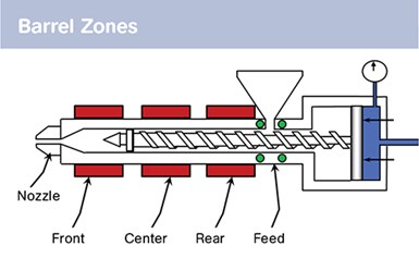
FIG. 1 Shown here are the four basic barrel zones on an injection molding machine that must be set up properly, along with the nozzle body and tip.
Even if it’s a material you have experience with, double-check data sheets for the resin supplier’s recommendations. A mistake at startup will only screw up the rest your day and cost your company money. Usually the resin supplier will provide a range: Let’s say it recommends 450-510 F (230-265 C) for a semi-crystalline resin. Pick something near the center, in this case 485 F (250 C). You now have the target temperature for the melt. Next is setting up the barrel zone profile.
This is a bit more complicated. A molder will often consider what backpressure to use in setting up the barrel temperatures. While important, backpressure deserves a separate article. For this discussion, let’s assume it is set at 700 psi plastic (not hydraulic) pressure, as this resin is reasonably thermally stable and not glass-filled. Backpressure cannot be stated as 50 or 100 psi, as a hydraulic machine has an intensification ratio that must be known and used to set backpressure correctly if you want to duplicate the process. In my experience, backpressure is stated incorrectly in 95% of resin suppliers’ specification sheets.
Before the barrel zone profile is established we need to cover a couple of resin and screw basics. These will help us understand the barrel profile settings. The typical “general-purpose” screw in our industry is best described as having no purpose. In the real world, however, such designs are common.
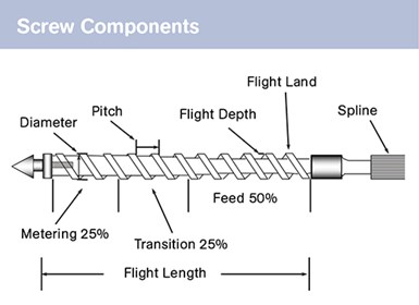
FIG. 2 Typical molding machine screws consist of three sections, as shown here.
A screw is composed of three sections (Fig. 2):
1. The feed zone. Often half the screw flight length, this section augers and compacts the granules coming in from the feed throat and perhaps conducts a bit of preheating before the transition zone. Feed-section flights are deep, and as the granules fall in there is air between them. This air needs to be vented out the feed throat or it will cause problems such as splay.
2. The transition/compression zone. This usually comprises 25% of the screw flight length. Here material is melted for the shot.
3. The metering section. This also is typically 25% of the screw flight length. This section pumps the plastic forward and generates the backpressure.
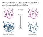
Semi-crystalline resins melt very differently from amorphous resins.
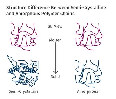
With screw basics completed, let’s turn to resin issues that influence how plastics melt. Thermoplastic resins can be amorphous or semi-crystalline. Amorphous materials like ABS and HIPS melt gradually, like butter, and soften easily. Conversely, semi-crystalline resins like polypropylene, polyethylene, and nylon melt like ice, and stay hard until they reach their melting point. They also have a latent heat of fusion, which means they need a certain amount of energy to reach their melting point, and once there they need yet another jolt of energy to get them melted. A semi-crystalline resin will often require twice as much energy to melt as an amorphous resin. For example, PS takes about 160 Btu/lb to melt, whereas PP takes 250-300 Btu/lb. Bottom line: It is harder to properly melt a semi-crystalline resin.
So both screw and resin characteristics must be taken into account when setting up barrel zone temperatures. How does one sort all this out?
•Setting the feed zone: Starting at the beginning of the melting process, the feed zone has to act as a vent, but you don’t want the granules to stick together. It should be PID controlled like the other zones, and for the semi-crystalline resin in this scenario I suggest 140 F (60 C). This is warmer than most would consider, but it provides venting, will not result in condensation of volatiles, is well below the softening point of the resin, and will not cause bridging.
•Setting the rear zone: Remember, in our scenario we are running a semi-crystalline resin, so you must consider shot size. If the shot is greater than roughly 50% of the barrel capacity, keep in mind that the feed section actually shortens because of the large shot size; that is, the time before the resin sees the transition or melting zone shortens. You also have to consider that the transition zone has to pump in a lot of energy and may not be able to get it done. Thus, if the shot is a large portion of the barrel capacity, I set the rear zone high, perhaps 490 F (255 C). If the shot is less than 40% of the barrel, the rear zone would be lower, 465 F (240 C), to ensure there is no melt formed in the feed section to block venting. For an amorphous resin I do not raise the rear zone.
•Setting the center and front zones: To achieve melt uniformity these are both set at the target melt temperature, 485 F (250 C). The goal is to have the front zone at the same temperature as the melt coming out of the metering zone. If the front zone temperature is different there will be a problem with melt uniformity. Review the details of the cycle and you will realize the shot—a cylinder of plastic and reasonably thick—does not reside in the front zone very long—only seconds. If the front zone is a different temperature than the melt, some portion of that cylinder of plastic will be at a different temperature, as plastic is a poor heat conductor.
The goal is that once you have the plastic melted, keep it at that temperature. The melt does not reside in the front zone, nozzle body, nozzle tip or hot runner long enough to reach melt uniformity if these are at different temperatures than the target. Having the outer layer of the plastic melt at a different temperature will often produce cosmetic issues with your parts. Blush, halos, gloss differential, etc., are problems I have found to be some of the hardest to resolve.
Avoid the ‘quagmire’ in setting up nozzle temperatures.
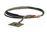
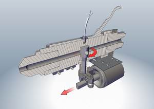
Setting the temperature of the nozzle body and tip is a quagmire. Most have incorrect heater bands, temperature controllers, and insulation, plus poor location of thermocouples and other design issues. All these problems make setting the right temperature nearly impossible.
My recommendation is to first set this up as I discussed in my column in the February 2013 issue (Don’t Ignore Nozzle Temperature Control). Then set the temperature at the target, purge a couple of shots, build a shot, and back the injection unit as far as it will go. Working with protective equipment, insert the longest thermocouple into the nozzle tip as far as it will go. Wait until the temperature stabilizes and extract the thermocouple by 2 in. (50 mm) and take another reading. Repeat this until the thermocouple is just inside the nozzle tip. If you see a temperature variation of more than 20° F (10° C), find the problem and repair it. If the temperatures are in the same ballpark, note the difference from the target and adjust the setpoint accordingly.
ABOUT THE AUTHOR: John Bozzelli is the founder of Injection Molding Solutions (Scientific Molding) in Midland, Mich., a provider of training and consulting services to injection molders, including LIMS, and other specialties. E-mail john@scientificmolding.com or visit scientificmolding.com.
Related Content
Five Quick Steps Toward Better Blending
Rising costs of resins and additives, along with higher demands for quality and use of regrind, place a premium on proficient blending. Here are some steps to get you there.
Read MoreKnow Your Options in Injection Machine Nozzles
Improvements in nozzle design in recent years overcome some of the limitations of previous filter, mixing, and shut-off nozzles.
Read MoreUltrasonic Welding: Tips, Techniques, and Troubleshooting
In this collection of content, we provide expert advice on welding from some of the leading authorities in the field, with tips on such matters as controls, as well as insights on how to solve common problems in welding.
Read MoreThe Effects of Time on Polymers
Last month we briefly discussed the influence of temperature on the mechanical properties of polymers and reviewed some of the structural considerations that govern these effects.
Read MoreRead Next
Injection Molding: Melting Amorphous vs. Semi-Crystalline Plastics
Understanding the differences in how each melts is crucial to obtaining melt uniformity.
Read MorePrecision Processing Requires Precision Equipment
Moretto offers plastics processors and micromolders for a broad suite of auxiliary solutions targeted specifically for precision processing.
Read More
.jpg;width=70;height=70;mode=crop)
