Are Your Sprue or Parts Sticking? Here Are Some Solutions
When a sprue or part sticks, the result of trying to unstick it is often more scratches or undercuts, making the problem worse and the fix more costly. Here’s how to set up a proper procedure for this sticky wicket.
With all the variables involved in molding, sprue or part sticking is not only frustrating but a profit killer. Production-floor personnel have enough to do without having to dig parts or sprues out of a mold. Finding why this happens is the only way to prevent future occurrences, but where do you begin? It’s not so simple, as there a number of possible causes.
First, set up a proper procedure for clearing a part or sprue. My bet is that 90% of the time when a sprue or part sticks, the effort of unsticking it results in scratches or undercuts, making the problem worse and the fix more costly. So spend some time training operators on the use of brass tools and the importance of not making matters worse.
If deep, thin ribs are sticking, modify the tool. It will cost a lot more if you don’t.
Also, if deep, thin ribs are sticking, modify the tool via draft, ejector pins, or some method. Don’t tell me this is too expensive; you’ll spend 100 times more on production loss. A good example happened to my training mold recently: An operator dug out a stuck rib with lineman pliers and slipped. The cost to repair the scratch on a high-polish mold is about $800. End of discussion.
The Sticky Sprue
Let’s start with a sticking sprue in a cold runner. Try this method:
1. Check that the orifice in the nozzle tip is smaller than the orifice of the sprue. The tip orifice should be at least 0.030 in. (0.75 mm) smaller in diameter than the sprue. I like using a pencil: Sharpen it, then stick it into the sprue-bushing orifice and mark the ring left on the soft lead. Now push it gently into the nozzle tip. You should have two rings on the lead, and the smaller one should be unmarked.
2. Check that the radius of the nozzle tip and sprue-bushing mate properly. You’d be surprise how often these radii do not match. They both might be a half-inch, but there still could be a mismatch. Note Figure 1. The pressure-sensitive film turns shades of red (the darker the shade the higher the pressure). The red ring at top indicates the nozzle tip is seating on the outside perimeter of the sprue bushing. This will cause a film of flash to form in this area, which in turn may cause the sprue to stick. It may also cause the injection unit to be pushed back during injection.
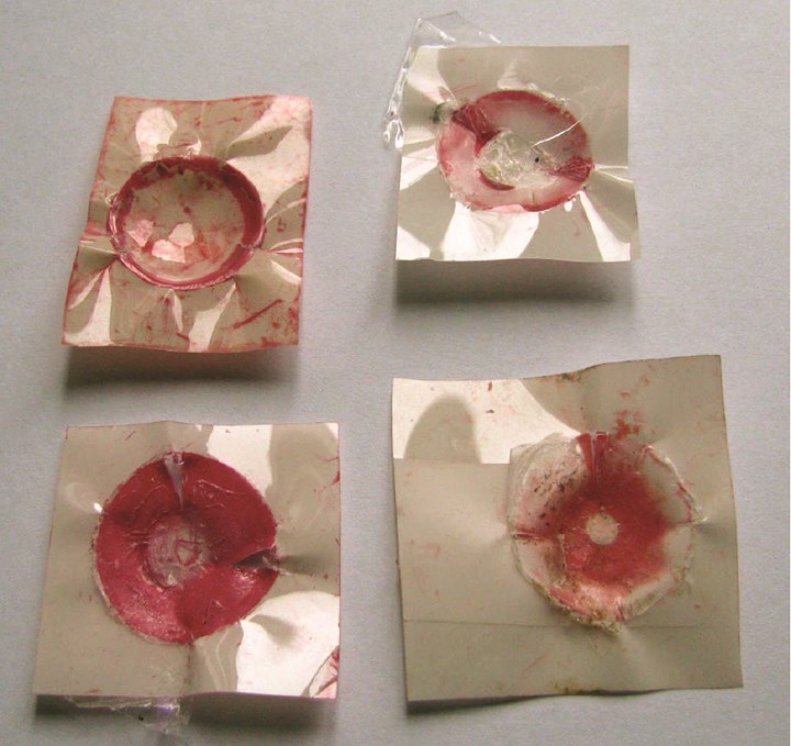
Fig. 1 You’d be surprised how often the radii of the nozzle tip and sprue-bushing don’t match. The red ring (indicating higher contact pressure) on the pressure-sensitive tapes at top indicates the nozzle tip is seating on the outside perimeter of the sprue bushing. This will cause a film of flash to form in this area, which in turn may cause the sprue to stick. The tapes at bottom indicate a better fit; 90% of all nozzle tips need to be mated to obtain this correct contact area.
At bottom is a better a better fit, and it is my experience that 90% of all nozzle tips need to be mated to obtain this correct contact area. You can use cardboard to test, but it does not provide as much information. Bring the nozzle tip up against the cardboard covering the sprue bushing. The nozzle tip should leave a smooth imprint on the cardboard, indicating a good mating pattern between components. If cardboard is cut or torn, change the nozzle tip.
3. Check that the nozzle tip is free of burrs.
How you polish the sprue could be a cause of sticking.
4. Check out the sprue for scratches and the correct polish. Draw polishing the sprue is critical—polishing in a back-and-forth motion in the direction of part ejection instead of a circular or elliptical motion. Circular polishing can create minute scratches that act as undercuts or gouges in the steel; these are known causes for sticking. If you are molding a soft-touch material, try vapor-honing (a variation of sandblasting).
5. There is also the chance that the sprue sticks due to high packing pressures required to form the part. Do a gate-seal study and see if you can take the high pack pressure off earlier, which may cause the sprue to shrink more and release easier. Check the pressure required to move plastic through the sprue. If it’s greater than 3000 psi, it might be too small and enlarging may help.
6. Check that the sucker pin is not worn or fouled and has been appropriately designed.
7. Is there resin plate-out or degraded material building up? If so remove, clean, and re-polish the tool. Find the cause and fix it.
8. Check the temperature of nozzle tip and/or nozzle body; they can be too hot or too cold. Measure the temperature with a long probe. Stick it in as far as it will go, measure temperature, then pull it out 2 in. (50 mm) and take another measurement allowing it to stabilize at each position. Continue until the probe is just inside the nozzle tip. If you see a temperature variation of more than 15° F (8° C), re-establish the positions of the thermocouple and heater band.
9. The tip may use the incorrect metal or design. Try a new tip and/or a different style, I prefer the “free-flow” style because of the shorter land, better flow pattern, and no dead space. However, it often needs a Kevlar insulator, not cardboard. Usually there are markings on the nozzle tip to indicate type.
10. Check taper of the sprue bushing, if the taper is 0.5 in./ft, try increasing the taper.
11. Check for peening in the nozzle tip and sprue bushing.
Parts Sticking: Tool Related
Figuring out why some parts occasionally stick can be something of a nightmare. Things are not always logical here. The part could be stuck in the moving side of the mold, but the cause can be in the stationary side. The part can have a problem releasing from the stationary side upon mold opening, and this slight distortion causes it to catch in the moving side upon ejection.
First find which side of the mold is causing the problem. The best way to find out is to record the mold opening and part ejection with a high-speed camera. The cause can easily be missed by the human eye even with slow mold opening and ejection. The cause can also be a slight distortion at the start of ejection. The part does not release evenly and distorts as a corner sticks, then releases, only to have the part catch on the other side.
A recording tells the story more clearly. Not everyone has access to high-speed video, but check out renting one for a half a day. If it’s a no-go for the camera, then close and open the mold as slowly as the press will allow, looking and listening for any telltale signs. Then, as slowly as possible, eject the part, paying close attention to when the ejector pins first start pushing on the part. You might need a vacuum release or air blow to solve the problem.
Another procedure to help define the problem is to remove the second stage by taking the second-stage or pack-and-hold pressure down to near zero. Does the part stick when it is short, or only when it is packed out? If it sticks when short there may be too much shrinkage, or perhaps there is a tool issue. If it only sticks when packed, there might be too little part shrinkage.
What else can cause parts to stick? Here’s my list:
1. Scratches can cause material sticking in the sprue, part sticking on the “A” side of the mold upon mold opening, or part sticking to the “B” side of the mold at part ejection. Again, scratches must be polished out, and polishing must be done in the direction of draw or mold opening.
2. Plate-out on the mold surface can cause sticking. Inspect the mold surface for buildup and clean appropriately. Actual process temperatures may be too high, so check actual melt vs. set temperature.
3. Is the polish correct or do you have too deep a texture? You need 1.5° of draft for every 0.001 in. (0.025 mm) depth of texture.
Both too high a polish or too deep a texture can cause sticking.
4. Too high a polish can cause parts to stick by creating a vacuum upon ejection. This is especially valid for soft-touch resins. Use a vacuum break or venting to aid release. Texture polish will also help ejection of soft-touch resins.
5. A mechanical source of trouble can be cocking of the ejector plate. Check for even length of the knock out bars, which should be within 0.003 in. of each other and use guided ejection. In addition, you may need more, larger or better-placed ejector pins.
6. Keep your ejection pressure down to a minimum; you will find out if a pin is galling and that could cause cocking of the ejector plate.
7. Check the part for areas that show stress whitening. These are sure signs of trouble; find what is causing this stress. More draft or larger ejector pin may be needed.
Parts Sticking: Process Related
Several process missteps can cause parts to stick:
1. Imbalanced filling, especially in a multi-cavity tool, can cause over- or under-packing issues and subsequent part sticking. Take time to do a proper short-shot study. Make a shot with no hold pressure where the largest part is only 80% full. Find the smallest and largest parts. The smallest part should be at least 80% of the weight of the largest. If not, balance the mold.
2. Excessive packing can also be a cause of part sticking. Overpacking the mold with plastic may limit shrinkage of the part, causing sticking. Reduce the pack or hold pressure and/or time if possible. Time taken from the second stage should be added to the cooling, cure, or mold-closed time to keep the cycle the same.
3. Also, try a longer and/or shorter cycle time to solve sticking by taking time off cooling or mold-closed time.
4. Underpacking the mold cavity can cause excessive shrinkage, which can also result in sticking. Increase the second-stage pack and hold pressures and time while decreasing cooling time to keep the overall cycle time unchanged. Extending the overall cycle time by lengthening the cooling or mold-closed time can work if you need more time for the part to shrink away from a cavity onto a core.
5. Improper gate-seal time or incorrect second-stage pack/hold time can also be a culprit. Perform a gate-seal test to determine if this is the cause.
Degraded materials tend to stick, so check the process temperatures.
6. Mold or material temperature can also be a source of problems. Degraded materials tend to stick, so check the process temperatures, especially at the nozzle where set and actual temperatures are often different. Try raising or lowering the mold temperature significantly as long as it does not cause mold damage. Water temperatures can be different but keep the steel temperatures between both halves of the mold within 20° F (10° C).
7. Cooling is 95% of the cycle so check the mold cooling lines for water flow rate, being sure that you achieve a Reynold’s number of 5000 or greater for turbulent flow and optimal cooling. The temperature difference between the inlet and outlet water lines should be less than 4° F (2° C).
8. Prevent contact with chemical solvents or mold sprays that can attack certain resin types.
9. Inadequate or no mold release in the resin can also be a cause of sticking. Adding a mold release to the resin can assist. There are very effective siloxane masterbatches that can be blended with certain resins to aid in part release.
Related Content
Process Monitoring or Production Monitoring—Why Not Both?
Molders looking to both monitor an injection molding process effectively and manage production can definitely do both with tools available today, but the question is how best to tackle these twin challenges.
Read MoreOptimizing Pack & Hold Times for Hot-Runner & Valve-Gated Molds
Using scientific procedures will help you put an end to all that time-consuming trial and error. Part 1 of 2.
Read MoreHot Runners: How to Maintain Heaters, Thermocouples, and Controls
I conclude this three-part examination of real-world problems and solutions involving hot runners by focusing on heaters, thermocouples, and controls. Part 3 of 3.
Read MoreKnow Your Options in Injection Machine Nozzles
Improvements in nozzle design in recent years overcome some of the limitations of previous filter, mixing, and shut-off nozzles.
Read MoreRead Next
Tooling: Critical Design Considerations for Sprue Bushings
Among them are good cooling, proper orientation, solid retention, structural integrity, generous radii, and an appropriately polished bore.
Read MoreTooling: Know the Basics of Sprue-Puller Design
Sprue-puller designs are quite varied, and there are no firm rules to follow. But here are some important cautions and caveats to keep in mind.
Read MoreSticking Sprues or Parts? Lots of Possible Causes and Solutions
Material sticking in the mold can be a production killer, whether it is the sprue or the formed part in the cavity.
Read More
.jpg;width=70;height=70;mode=crop)
