
Extrusion: Enhanced Deckle Boosts Coating Productivity
Simplified mechanisms for Nordson EPC die streamline the adjustment of coating width while reducing the size of edge bead.


Nordson has streamlined the design of the EPC deckle system for EDI extrusion coating and laminating dies to make it easier to control edge bead and reducing downtime for width changes and cleaning.
The widely used EPC die includes an internal deckle system that reduces resin cost and trim waste by controlling edge bead formation, plus an external deckle for convenient width adjustment. The new enhanced design provides these improvements:


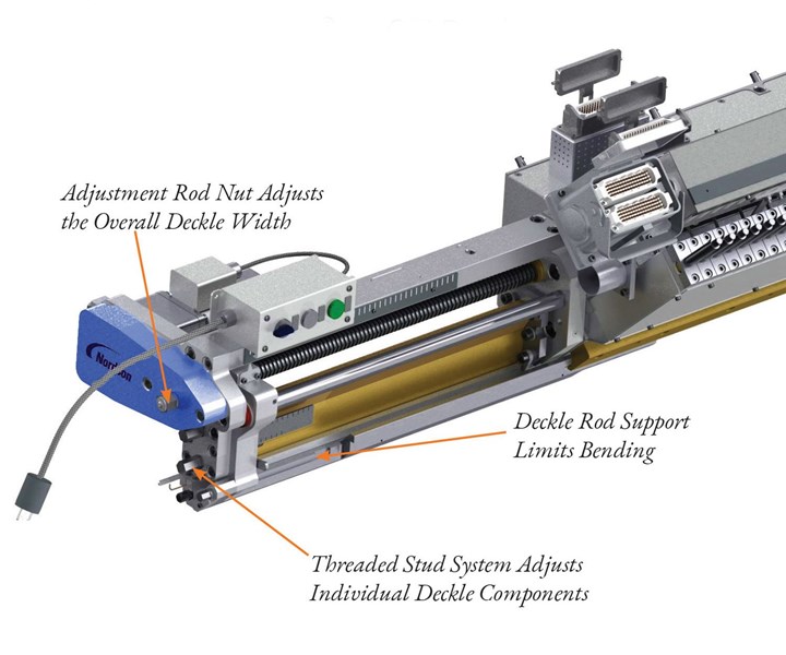
● Easier control of edge bead: For independent adjustment of the internal deckle components, Nordson has replaced a rack-and-pinion gear with a threaded stud that makes it easier to fine-tune the edge bead, reducing the amount of trim required and increasing material savings.
● Easier manual adjustment of deckle width: Nordson has replaced a gear box used for adjusting overall deckle width with a nut on the adjustment rod, reducing the width and weight of the deckle system and increasing access for operators.
● More robust and user-friendly construction: A durable new deckle rod support guide makes deckle adjustment easier.
● Easier access for cleaning and maintenance: A low-profile external deckle can be removed as a single unit, or it can slide out for installation of a lip scraper without removal of the entire deckle assembly. Similarly, internal deckle components can be taken out by removing six bolts from the end of the deckle system without disengaging the entire unit.
The internal deckle system in an EPC die provides fine-tuning of the edge profile of a coating. The molten polymer in a die without an EPC deckle system will exhibit transverse flow, producing an enlarged edge bead from the resulting necking at the die exit. In the EPC system, the internal deckle components for adjusting the edge bead profile are located downstream of the primary manifold—one in the preland section, the second in the secondary manifold. By adjusting the positions of these components relative to one another, it is possible to reduce the flow of polymer at the extreme edges of the coating, thereby minimizing edge bead.
Related Content
-
Cooling the Feed Throat and Screw: How Much Water Do You Need?
It’s one of the biggest quandaries in extrusion, as there is little or nothing published to give operators some guidance. So let’s try to shed some light on this trial-and-error process.
-
Fully Automated Extrusion Process Enables Use of Composites for Manufacturing Pressure Tanks
Amtrol was looking for a more cost-effective means to produce thin-wall liners for a new line of pressure tanks. With the help of a team of suppliers, they built one of the world’s most sophisticated extrusion lines.
-
How Much L/D Do You Really Need?
Just like selecting the extruder size and drive combination, the L/D should be carefully evaluated.


