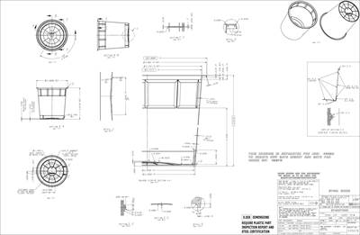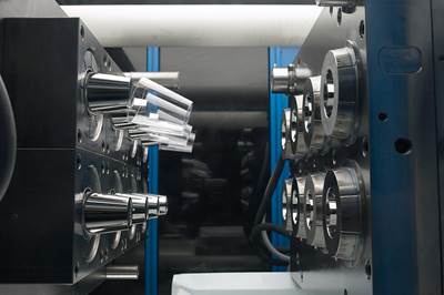
Figure 1: Example of engraved products.
Source All Images) | Carl Hanser Verlag Munich
Engraving encompasses lettering, lines, ornaments, logos and other types of identification or other markings of a plastic part. Engravings in the mold represent a one-time cost. So, in the long run, the cost of the finished product is less than the cost of applying labels to the molded product or printing the parts. However, an engraving on the molding surface will have limitations such as color, depth, size and location (see Figure 1).
If labels are applied in a separate operation, add this cost to the product's cost. In-mold labels are vibrant in color but slightly more expensive than standard multi-color dry offset printing. In either case, the cost of the labels, or ink and additional equipment, must be added to the part cost.
Remember that the same product could be used for different end-user applications. For example, containers of the same size could be used to sell different chemicals to different manufacturers. In both cases, applying labels after molding would make more sense rather than changing mold components for a different engraving.
Whether to use engraving throughout, labels alone, or a combination of both, should be decided based on the quantities of pieces to be produced and the required flexibility in each case. As a general guideline, the cost of the molded product increases approximately as follows:
- Engraving: Negligible amount
- Printing: By five to 10%
- Labeling: By 15 to 30%
Assuming the decision has been made to engrave the parts, the following rules of thumb and best practices should be considered when engraving your cores and cavities.
Depth
It is important to understand engravings that are to appear depressed (appearing engraved) in the surface of the product are created by raised features in the mold. Conversely, raised features in the product are created by depressed (engraved) features in the mold. It is fairly easy to engrave into a steel surface, but very time-consuming and costly to create engravings projecting from a surface.
Figure 2: (Top) Raised engraving on top of a product. (Bottom) raised engraving in a depressed panel. t = Wall thickness of the product; H = Height (depth) of engraving.
The only time it may be necessary to have the engraving depressed in the product is when the lettering will be filled with paint after molding, for better readability, special effects or artistic designs, usually associated with high-quality products, such as cosmetics containers.
Engravings should be no deeper than H=0.25 mm (0.01 inch). The width of the engraving should be 1.5-2 × the depth, and the engraving should have an angle of 30° on all walls for ease of ejection and visibility (see Figure 2).
Font Style and Size of Artwork
To be readily legible, the minimum size of molded-in lettering is eight points, but six points could be used in exceptional cases. The recommended depth is 0.08 to 0.13 mm (0.003 to 0.005 inch).
In all cases of engravings, it is also important to consider the cost of removing the burrs (by hand or mechanically) after cutting the steel to prevent unsightly, fuzzy outlines of the engravings on the molded products.
Polarity
We shall define positive engraving as any engraving that will appear readable to the user. Negative engraving is the inverted image, e.g., as ordinary lettering would appear in a mirror. Most engravings are viewed from the outside of the product (top, side or bottom), regardless of whether the plastic is opaque, transparent, or translucent. In all these cases, the engraving must be negative to appear in the molded piece as readable (positive).

Figure 3: Gate pad engraving in steel and in the bottom of a molded container.
This is important where the features of the engraving may not be so obvious, such as the case of logos or trademarks, which may appear to the casual observer as symmetrical but may have some asymmetrical features, which the user must see in the proper orientation (polarity).
In some products molded from transparent or translucent plastics, the required lettering or marking could be molded on the inside of the product so that the user can read it through the plastic. In these cases, the engraving must be positive in the mold steel (see Figure 3).
Location Selection
The product designer usually places the lettering, lines, or symbols at locations where they are best suited for the end user, but occasionally, such engravings could be difficult for the mold maker to produce in the location specified. This could be where engraving inside a pocket in the mold would be difficult or even impossible and would require inserts or EDM with special electrodes.
In some cases, the engraving could be too close to the edge of the mold steel, thereby increasing the risk of early failure of the mold steel due to stress cracks. A minimum of two mm between any engraving and the edge of the mold steel is suggested.
Walls and Bottoms of Products
Engravings can be on the cavity wall or on the core (they could also be on inserts in either the cavity or core). In either case, the engraving must be designed so that the part will easily be released from the cavity during mold opening and ejected from the core.
Outside of the Product (Engraved Cavities)
Containers usually require markings on the outside of the sidewalls or in the bottom. Markings at the bottom are often required to show trademarks, patents, product identifiers, batch identifiers, dates of manufacture, or others. Engravings on the sides are occasionally required (usually with transparent or translucent plastics) to indicate liquid levels inside a container.
Engraving into the bottom of a cavity is usually not difficult to manufacture, especially if most of the bottom of the cavity is an insert in the cavity block (Figure 3). Alternatively, it is not too difficult or costly if inserts with the required engravings are placed either in the solid cavity bottom or within a large cavity bottom insert (creating inserts within an insert).
However, serious challenges can arise when laying out the cooling circuits in such complex cavity bottoms. Good cooling in the gate area is very important for fast molding cycles, and inserts make it more difficult to lay out efficient cooling channels. A poorly cooled cavity bottom, especially near the gate, will result in a longer molding cycle.
In this case, the preferred method is to have a solid insert for much of the cavity bottom. If changes are required in the engraving, changing the bottom is not too difficult or expensive. However, this may result in having and storing several different bottoms for the cavity for the various applications or end users of the product, which are also costs to be considered.
Mechanical engraving in the bottom of deep cavities is difficult because long, unsupported engraving cutters must operate at a slower speed for the required accuracy and cleanliness of cut. Long EDM electrodes can be used, although they are slow and expensive. However, this method has the advantage that it can be done even after the cavity is finished.
As it cools inside the mold, the injected plastic shrinks away from the cavity wall. If the depth of engravings into the cavity walls is not too deep, there is usually no problem with ejection. As the product shrinks toward the core, it will not hang up in the cavity as the mold opens.
However, the clean withdrawal of the molded piece from the cavity also depends very much on the draft angle of the sidewall, the wall thickness of the product in this area, and the type of plastic used.
Any engraving (by chip removing or EDM) in the sidewall inside a cavity, especially in a small one, is very difficult and expensive. Shallow engravings burnt with EDM are easier to achieve. Still, there is the problem of matching the engraved electrodes to the shape (curvature) of the cavity wall so that the depressions created with EDM are uniform both in depth and appearance and do not exceed the critical depth beyond which the product cannot pull out of the cavity. The suggested maximum depth is 0.1 mm (0.004 inch) or even less for difficult cases, such as those explained in the following points.
Walls with heavier thickness allow deeper engravings because they shrink more and let the product withdraw more away from the cavity. The greater the shrinkage factor, the easier the engraved portion pulls away from the cavity.
The greater the taper of the sidewalls, the easier the product will pull out of the cavity. Engravings in sidewalls with tapers of less than approximately 5o are more difficult to withdraw than from walls with larger tapers.
Hard plastics such as PS will offer more resistance than more flexible plastics such as PP if they are caught by the edge of too deep a depression. This will show up as drag marks on the part. However, many molds successfully produce even thin-walled PS products with decorations on their outside walls.
The angle and shape of the sides of the engraving within the cavity's sidewall must offer little resistance as the mold opens, and the edge of the engraved projection in the product slides past the engraved depression in the sidewall.
Any deeper engravings in the side walls or where there is not enough draft angle will require the designer to place the engravings either on moving side cores in the cavity or on split cavities. Both methods would require more space and much larger molds and add considerably to the mold cost. Such molds will usually also potentially produce more scrap, require longer molding cycles, and thereby increase the cost of the product even more.
Figure 4 shows heavy-walled tumblers engraved with an artistic pattern on the outside, produced by engraving (texturizing) the inside of the cavity. This engraving is not deep enough to require a split cavity.

Figure 4: Tumblers engraved on the outside.
Inside of the Product (Engraved Cores)
Engravings on the sides are often required with transparent or translucent plastics, e.g., to indicate liquid levels inside a container (measuring cups, vials, etc.). The markings are usually lines indicating the proper height and lettering to identify the values. Such products are made mostly from clear PS, SAN, acrylic or PC with low shrinkage factors. This makes it relatively easy to calculate the dimensions where the measuring lines should be located. If such products are made from high-shrinkage materials, such as PE or PP, the high shrinkage factor makes it more difficult to predetermine the proper location for the level markers.
In such cases, especially if the accuracy of the measuring lines is important, it may be necessary to finish the mold first, complete with the lettering, but to engrave the measuring lines only after the mold has been tested and run on an optimal cycle because the volume of the container can vary substantially when operating at different operating conditions of the mold.
Except for very stiff plastics (such as PS, SAN or PC) or sometimes for air ejection of softer plastics, lines and lettering on the core present fewer problems because the plastic will stretch during ejection and let the plastic slide out of the engravings. This is possible because the cavity has already moved away from the product at the time of ejection, and there is ample room for the plastic to stretch during ejection.
However, the deeper the engraving, the more important it is to ensure that the sides of the engravings are tapered and/or rounded sufficiently to allow easy sliding out of the engravings. The draft of container sidewalls can be quite small. A1° taper could be acceptable, as long as the engraving is not too deep and the side of the engraving in the direction of the ejection is smooth and chamfered or rounded.
Engraving into the side of a core is usually not difficult to achieve. The depth should be 0.1 mm, but less is recommended for small draft angles (less than 1o) of the core. While it is feasible to produce raised engraving on the core, it is extremely difficult to machine and then finish the molding surface of the core, and the mold would, therefore, be very expensive.
The top of the core can be a good location to engrave the cavity number. This is easy to produce and is frequently done in technical products and enclosures. The designer must be sure that it can be easily read. If it is to be read from the inside, the engraving must be negative, whereas if it is to be read from the outside (through the plastic), the engraving must be positive.
Using these simple suggestions and reminders can make the markings on your mold effective, eye-catching and low-cost.
*This article is based on information from the “Injection Mold Design Handbook,” Carl Hanser Verlag Munich, 2021. To learn more practical tips and guidelines for good mold design, visit hanserpublications.com or Amazon.
Related Content
Where and How to Vent Injection Molds: Part 3
Questioning several “rules of thumb” about venting injection molds.
Read MoreThree Key Decisions for an Optimal Ejection System
When determining the best ejection option for a tool, molders must consider the ejector’s surface area, location and style.
Read MoreUnderstanding Melting in Single-Screw Extruders
You can better visualize the melting process by “flipping” the observation point so the barrel appears to be turning clockwise around a stationary screw.
Read MoreThe Importance of Melt & Mold Temperature
Molders should realize how significantly process conditions can influence the final properties of the part.
Read MoreRead Next
MMT Chats: Giving Back by Answering the Moldmaking Education Need
MoldMaking Technology Editorial Director Christina Fuges checks in with Bruce Cateon, an executive advisor at OASIC Consulting. Bruce started out in moldmaking, eventually becoming an industry consultant and taking time to work on his passion project the “Injection Mold Design Handbook” as a way of giving back to the industry that has given him so much. This episode is brought to you by ISCAR with New Ideas for Machining Intelligently.
Read MoreIt Starts With the Part: A Plastic Part Checklist Ensures Good Mold Design
All successful mold build projects start with examining the part to be molded to ensure it is moldable and will meet the customers' production objectives.
Read MoreDeliberate Mismatches for Easier Mold Manufacture and Improved Part Appearance
Basic principles for applying deliberate mismatch in the area between the core and cavity and between two matching plastic parts.
Read More

