INJECTION MOLDING: Why Pellet Size and Shape Are Important
Uniformity is needed to help ensure melt quality.
There are hundreds of details in the injection molding process and in evaluating them I can get rather “picky.” This month I’m picking on the pellets. Regardless of the resin type or manufacturer, you as a molder want your pellets to be uniform in size and shape. But pellets vary in size and shape. In the case of regrind they can range from fines to larger chunks. Bottom line, you need all the pellets to be uniformly melted at the proper temperature. If your pellets range in size and geometry, this won’t happen. Non-uniformly melted resin will not yield uniformly good or identical parts…period. (By pure coincidence, Jim Frankland discusses this very subject in his Extrusion Know How column here.)
My guess is that the majority of molders do not give this issue much thought. Admittedly, it’s not the first thing I check when troubleshooting a problem, but I need to bump it up a few rungs. We assume all is well because we see molten polymer come out of the nozzle when we purge the machine, or because the parts look OK. That’s a bad assumption. To understand the problems with melting non-uniform pellets, let’s look closer at the melting process.
The melting process starts with the hopper, which feeds the granules into the feed throat. The hopper should be designed to provide mass flow—not funnel flow—so that resin is fed uniformly to the feed throat. There must be no channeling in the center, which is known as funnel flow (or “rat-holing”). Take a reality check: Go out to the shop floor and watch the pellets through the cleanout window. If the pellets up against the window do not slide down into the feed throat, you have a problem. My bet: 95% of the time, those pellets stay there for the entire run.
So how do you ensure mass flow? Check the hopper angle; for mass flow: It should be angled 60°. Single-shot hoppers are fine, provided you do not see fluidizing of the pellets (dancing in an air stream) when it calls for resin. If fluidizing occurs during screw rotation, you can guarantee the next shot will be a different part, because the fluidizing keeps some pellets from settling into the intake screw flights. This is a process variation. If you do have fluidizing in single-shot hoppers, fix the air leak at the junction of the feed throat with a good high-temperature silicone gasket.
Once you’ve established mass flow, make sure your feed throat is clean, unobstructed with big chunks, fines, or streamers, and is PID temperature controlled. Erratic water flow in the feed throat is not acceptable; it’s the most important zone of the process. It also should be set at a higher temperature than you think. The feed throat has two jobs: Feed the resin, and —just as importantly—act as a vent for gases escaping from the feed section of the screw. Set it at 55-65 C (130-150 F) to allow volatiles to escape and not condense. Even polypropylene will not get tacky at these temperatures.
If you have bridging problems, note the composition of the bridged material. If all the individual granules are stuck, then the feed throat is too hot. But if there is any completely melted polymer, or if the bridge is a ball of solid plastic, you do not have a feed-throat temperature problem. More likely your non-return valve is leaking.
Now let’s turn our attention to the feed section of the screw. As the screw rotates, it picks up the granules from the feed throat and augers them through the feed section of the screw. On a general-purpose screw, the feed section is a whopping 50% of the flight length. The purpose of the feed section is to compact the pellets and prepare them for the transition section (also called the compression zone). Here is where the flights of the screw pick up the granules, and they have to fit into the flight chamber. Pellets falling into the flight are no problem, unless they are either very large or very small (fines).
If the pellet is so large that it stands taller than the flight, it may or may not be sheared between the flight and sharp edge of the bottom of the feed throat. This can actually force the screw back, not allowing the flight to fill completely with granules. The screw just augers backward and you do not have a full shot of plastic in front of the screw. This is common with small-diameter screws and/or use of low backpressures. The result is the next shot has splay, bubbles, shorts, or unmelt.
Fines pose a different type of problem, as they melt much faster and earlier than normal-size pellets, which in turn reduces the friction needed to melt the normal pellets. Results are unmelt and black and white specks in your parts.
As the granules move through the feed zone, they begin to pick up heat of the rear zone, along with some compaction. This is when your friend Murphy—you remember Murphy’s Law—invites himself to the party. First, you have worry about where the air between the pellets is going as the pellets compact. If the melting process starts too early, air gets trapped and pushed through to the nozzle. The air shows up in your part as splay, which you may mistake for moisture. Running the feed throat hot and rear zone at the proper temperature allows the air to escape (vent) out the feed throat, perhaps taking along some moisture and other volatiles. Ask around if you don’t believe moisture and volatiles vent through the feed throat. Somebody will tell you a story of the feed throat burping pellets or, worse, being blown to or through the roof.
With compaction comes some pressure, but the high pressure (thousands of psi) develops within the transition zone. Here is where all the melting should happen. The transition section of the screw is where the root diameter tapers thicker to the metering diameter of the screw; this taper compresses the plastic against the barrel wall. The ratio of the volume of a feed flight to the volume of a metering flight is known as the “compression ratio.”
Here is where the size and geometry of the pellets become driving factors on how and when a pellet or granule melts. Any variation in geometry or size will cause different degrees of friction, and this in turn provides non-uniformity within the polymer melt.
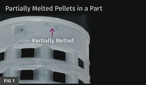
My bet is that variation in pellet size and geometry influences so-called “solid-bed breakup, ”a disruption of uniform conversion of the “solid bed” of compacted pellets into a melt pool within the screw flights, which is the source of partially melted pellets in your parts (see Fig. 1). My guess is that nearly 70% of your parts have this problem.
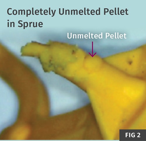
Different coefficients of friction will generate different melting patterns as the pellets travel down the screw. And when Murphy is feeling particularly mischievous, you can get completely unmelted granules in parts. This is a rare occurrence but it does happen (see Fig. 2).
Bottom line: Non-uniformity in pellet size and geometry fouls up the melting process and is a source of cosmetic, physical, chemical, and performance problems.
Related Content
The Effects of Time on Polymers
Last month we briefly discussed the influence of temperature on the mechanical properties of polymers and reviewed some of the structural considerations that govern these effects.
Read MoreThe Effects of Stress on Polymers
Previously we have discussed the effects of temperature and time on the long-term behavior of polymers. Now let's take a look at stress.
Read MoreThe Importance of Barrel Heat and Melt Temperature
Barrel temperature may impact melting in the case of very small extruders running very slowly. Otherwise, melting is mainly the result of shear heating of the polymer.
Read MoreHow to Optimize Pack & Hold Times for Hot-Runner & Valve-Gated Molds
Applying a scientific method to what is typically a trial-and-error process. Part 2 of 2.
Read MoreRead Next
Making the Circular Economy a Reality
Driven by brand owner demands and new worldwide legislation, the entire supply chain is working toward the shift to circularity, with some evidence the circular economy has already begun.
Read MorePeople 4.0 – How to Get Buy-In from Your Staff for Industry 4.0 Systems
Implementing a production monitoring system as the foundation of a ‘smart factory’ is about integrating people with new technology as much as it is about integrating machines and computers. Here are tips from a company that has gone through the process.
Read More
.jpg;width=70;height=70;mode=crop)
