Medical & Auto Molder Explores New Tech for Tooling & Cooling
Additive manufacturing and liquid-CO2 spot cooling are the firm’s newest tools for boosting productivity and quality.
Sinks, over-long cycles, “impossible” cooling challenges like getting water inside a long, thin core pin every molder has faced them at one time or another. Until recently, the options for dealing with such issues have been limited. But as one custom injection molder has discovered, new tooling and cooling technologies shatter old preconceptions of what is possible.
PTI Engineered Plastics, Macomb, Mich., is a privately held firm, founded in 1984. Its business is about 50% medical and 35% automotive, with the rest encompassing defense, electronics, and consumer products. PTI operates a 155,000 ft² plant with 46 presses from 12 to 750 tons. Since 2012, the plant has added 100 employees, bringing the total above 250.
Half the company’s business is prototype and short-run jobs. “Our sweet spot is 50,000 to 150,000 parts,” says Scott Kraemer, directing manager of corporate design, new technology, and Tech Academy. “We have medical customers who do only 5000 to 20,000 parts a year, but they are production parts.”
PTI uses primarily QC-10 aluminum molds—which it builds in-house—for prototypes and short runs. For long-run jobs, PTI also designs and builds steel tools or “hybrids” with aluminum mold bases and steel inserts.
As Kraemer’s long job title suggests, “I wear a lot of hats.” Two of those include responsibility for mold design and new technology—which come together in two recent additions to its technology toolkit, both of them having roles in overcoming mold-cooling challenges. (His third responsibility is for PTI’s “school” to teach high-school students about careers in manufacturing.)
LIQUID CO2 SPOT COOLING
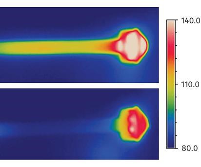
PTI Engineered Plastics is a success story for liquid CO2 (LCO2) spot-cooling technology that has been used in Europe for several years and was introduced to the U.S. in 2012 by Linde North America, Inc., Murray Hill, N.J. (see Jan. ’13 Close-Up). This involves delivering LCO2 under pressure to areas of the mold where heat is difficult to remove with conventional water cooling. Once released from a pressurized tube, LCO2 expands into a “snow and gas” mixture at around -79 C (-110 F), which has high cooling capacity due to the phase-transition energy from solid to gas.
“Liquid CO2 can enter small spaces where it’s hard to get water in,” says Kraemer. “And the good thing is that you don’t have to worry about a return line to get the CO2 out, because it becomes a gas that vents from the tooling.”
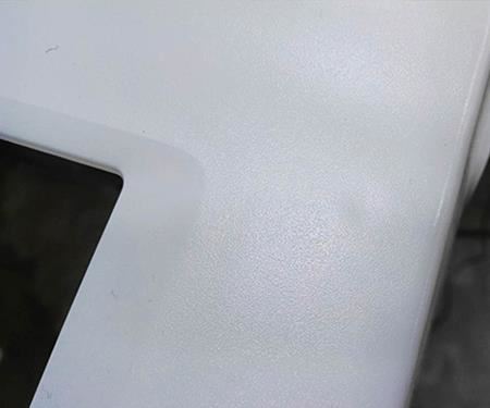
In the past year or so, PTI has used LCO2 spot cooling on more than a half-dozen molds with eight to 48 cavities. One example is a polycarbonate machine panel for a medical-equipment customer (photo). The panel is 15 x 18 in. x 2.5 in. deep. It had a sink problem that was solved by spot cooling through a core pin. “It removed the sink with no change in cycle time,” says Kraemer.
Another example he cites is a medical part in clear nylon, 0.25 in. diam. x 1.5 in. long. It has a core pin of 0.100 in. diam.. “There was no way to water-cool inside that,” Kraemer states. At 38-40 sec, the part was exceeding the quoted cycle time. So we cut a hole in the pin and injected LCO2. The cycle went down to 26 sec.”
Kraemer is looking at more “problem tools” with quality problems or excessive cycle times as candidates for LCO2 spot cooling. He is also starting to design molds with LCO2 cooling built in from the start. “It allows us to get cooling in where we couldn’t before.” Kraemer is interested in experimenting with LCO2 in conformal cooling channels that hug the contours of the part.
LASER-SINTERED TOOLING WITH LCO2
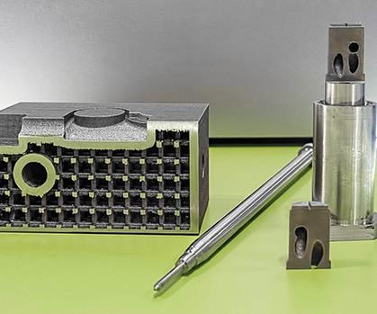
One way to design tooling components for LCO2 spot cooling is through additive manufacturing (also known as 3D printing). Building a cavity insert or other component up in thin layers from powdered metal allows you to incorporate cooling channels of any shape in any location—at no extra cost.
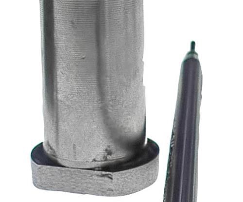
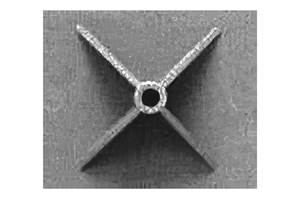
In experimenting with direct metal laser sintering (DMLS) since last October, Kraemer has built core inserts 3 in. diam. x 7 in. long with conformal cooling inside. Pictured here is a long core pin made with DMLS that has 0.040-in. water channels in and out. In order to get cooling most of the way down to the 0.100-in.-diam. tip, Kraemer built a second version of the core pin with 0.040-in. channels for LCO2.
Kraemer also found that DMLS allows building tool inserts with a lattice structure when high strength is not an issue. Eliminating as much metal as possible makes the component lighter in weight and potentially faster to cool. As this article went to press, Kraemer was starting trials with a lattice-built tool insert with built-in LCO2 spot cooling.
Related Content
How to Reduce Sinks in Injection Molding
Modifications to the common core pin can be a simple solution, but don’t expect all resins to behave the same. Gas assist is also worth a try.
Read MoreCaptive Molder Beefs Up Auxiliaries to Boost Quality, Consistency
SeeScan adds conveying, drying, feeding and chilling technologies to improve quality — and enhance employee safety — in production of its underground/underwater inspection systems.
Read MoreMulticoupling Range Extended
Hasco‘s quick-connect system for multiple cooling circuits has added U.S., French and HT versions.
Read MoreSystem Offers 'Lights Out' Mold-Channel Cleaning & Diagnostics
New system automatically cleans mold-cooling lines—including conformal channels—removing rust and calcium, among other deposits, while simultaneously testing for leaks, measuring flow rate and applying rust inhibitor.
Read MoreRead Next
Liquid CO2 Spot Cooling Gets Into Tight Spots in Molds
Cooling of long, thin cores, fillets, slides, ejectors, or other hard-to-reach spots in injection molds can present difficult challenges.
Read MoreFor PLASTICS' CEO Seaholm, NPE to Shine Light on Sustainability Successes
With advocacy, communication and sustainability as three main pillars, Seaholm leads a trade association to NPE that ‘is more active today than we have ever been.’
Read More

