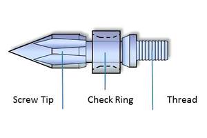
Pay Attention to Your Nozzle Body & Tip
These are overlooked components that can cost you thousands.
There are hundreds of details within injection molding; the problem is sorting out which ones are costing you money or keeping you from meeting critical tolerances. One that costs our industry a hundred thousand dollars a day is lack of attention to the nozzle body and tip of an injection molding machine. Every machine has one, and every day some of them give processors fits, resulting in long color or resin switchovers, drooling, stringing, part cosmetic problems, freezing off, leaking etc.
The purpose of the nozzle body and tip is to provide a flow path for the molten plastic from the end of the barrel to the sprue bushing of the mold. Sounds simple, and many molders treat it that way. However, ignoring these critical details can be costly:
•Pressure drop—make sure it is minimized.
•Temperature control with no hot or cold spots;
•Proper match-up or mating with the sprue bushing.
PRESSURE DROP
The injection unit typically provides plastic pressures in the range of 10,000 to 40,000 psi for filling and packing most parts, including thin walls. In many cases, the higher the pressure drop, the more difficult the molding—or any problems with the part or mold get amplified. Anything that can be done to reduce the pressure required will improve the robustness of the process. Ideally, the pressure drop on the entire flow path to the part is minimal. Yet most molders worry only about the runner system or gates, and even get a mold-flow analysis to make sure. Ever see any mold-filling studies on nozzle design?
The first recommendation is to keep the nozzle body as short as possible, resulting in lower pressure loss. That might be obvious, but I have seen nozzle lengths everywhere from 50 mm to 760 mm. The 760-mm nozzle body required more than 13,000 psi to get plastic to flow through it.
The flow path through the nozzle should be tapered or conical—not a straight bore—in order to provide the least pressure drop and allow for faster purging. Yes, the shape of the flow path can help or hinder color or resin changeovers.
To be fair, if it is a long nozzle body it is difficult to have one thick enough to taper. Also, the nozzle body may have a melt filter or mixing elements, which also add to the pressure drop. These should be evaluated for function and pressure loss so you know which filter is best and provides the least pressure loss. Also, if you watch the pressure loss, you can tell when the filter needs changing.
TEMPERATURE CONTROL AND SETPOINT
Most molders agree that melt temperature is important, and the nozzle body and tip are no exceptions. During first- and second-stage injection, pack, hold, and cooling, the polymer in the nozzle body should be kept at the same temperature as the melt from the barrel. Residence time in the nozzle is not long enough for the melt to achieve a homogeneous temperature there via thermal conduction alone. So if the heater bands are too hot, the material on the outside will get overheated. The result is often that you’ll notice a blush, halo, or other cosmetic flaw on molded parts.
Also, for most applications, the volume of resin in the nozzle body and tip is only a portion of the part, and if you want to prevent warpage, blushing, or gloss variations, the melt temperature and cooling have to be uniform. Since the goal is uniform temperature, logic would lead you to set the temperature of the nozzle body at the same setpoint as the barrel, but like many details in life, logic seldom prevails.
Good nozzle temperature control requires attention to the controller, thermocouple, setpoint, and heater size, design, and placement, as well as some consideration of heat conduction. A good PID auto-tuning controller should work fine. If the machine has spare temperature controllers, use them.
Thermocouple placement is a huge issue in our industry, as we have no standard for it. Some have a hole in the hex of the nozzle body. Others have it on one of the heater-band clamp nuts. Most molders rightly do not put a thermocouple through the nozzle into the melt stream.
So where should it go? Ideally we would have a sensor that is flush with the melt stream that provides instantaneous readings. So we are left with a compromise: If the nozzle body is less than 50 mm long it is okay, though not ideal, for the thermocouple to go in, not on, the hex of the nozzle body. If longer than 50 mm but shorter then 250 mm, buy a butterfly-type thermocouple and place it, using thermal paste, on the nozzle body one-third of the distance back from the nozzle tip. Wrap it two or three times with glass tape for insulation and replace the heater band, covering the thermocouple. If there is a hole drilled through the length of the nozzle, slide the thermocouple to the appropriate position.
A thermocouple attached to a heater band is unacceptable. Heater bands should cover more than 90% of the nozzle body and be of the right wattage and style. It would be nice if nozzles had thermal pins running through the length of the nozzle body. Unfortunately most cannot handle high temperatures and will be ruined if an operator takes a torch to the nozzle body or uses it with a resin requiring a melt temperature greater than 585 F. In addition, please route the thermocouple and heater-band wires on the side or top of the nozzle/barrel; you don’t want them drooping down so they get covered with plastic during purging.
Now that we have the nozzle body recommendations, what about setpoint? Due to the variations of size, type, hook-up, etc., determining setpoint is a guessing game. Focus on the goal of keeping the melt in the nozzle at the temperature of the melt in the barrel. Sometimes that will mean setting a nozzle temperature as much as 50° F higher (or lower) than the melt exiting the barrel. Using all necessary safety procedures, make a purge with larger volume than the nozzle body, measure the melt temperature, and then insert a thermocouple at least halfway into the nozzle. Leave the thermocouple in the nozzle for at least 10 minutes to see what temperature it stabilizes at after the purge. Note the difference between that temperature and the purge melt temperature and adjust the setpoint to accommodate this delta between set and actual melt temperatures.
TIP MATING WITH SPRUE BUSHING
Next is the nozzle tip, the part that mates with the sprue bushing. Most of the time this is the 25-mm adapter that screws into the nozzle body. It’s too small for its own heater band. Unfortunately, that small tip has a large heat-loss tendency, especially when it’s mated with a cold sprue bushing. The nozzle tip temperature should be the same as the melt temperature, but that is difficult to achieve due to the heat transfer to the sprue bushing on cold-runner molds.
How many hours have you wasted dealing with drooling, stringing, or a tip clogged with unmelted polymer? All these problems are caused by the nozzle transferring heat to the cold sprue. Using cardboard as an insulator only helps for a few shots. Also, what about the cold slug that sometimes comes out with the sprue, and sometimes stays in the nozzle tip? On the next shot it does not always go into the cold slug well in the mold. This cold slug can and does go around corners and plugs gates. My suggestions:
1. Throw out all standard or “general-purpose” nozzle tips. Their land is too long and has dead space just inside the tip.
2. Use free-flow type nozzle tips or, if necessary, a reverse-taper design.
3. Check the surface contact of the tip against the sprue bushing to make sure the contact is on the inside of the radius and not contacting the entire radius. The best seal is with a small area of contact on the inside radius, but the contact area must be large enough not to peen the sprue bushing orifice. A smaller area of contact will transfer less heat from the nozzle tip to the sprue bushing. Contact force is often 5 to 15 tons. High contact pressure is needed to contain molten polymer at 40,000 psi in thin-wall applications. I’m assuming here that you have made sure the injection unit is centered to the sprue bushing.
4. Use an insulator designed for this problem.
Help us to get this problem solved. Give us your best guess as to how much these issues cost your plant per month. Maybe we can convince someone to work on this. We will report the numbers to you in two months.
Related Content
iD Additives Adds Technical Specialist
Ethan Ravotti has joined iD Additives as a technical specialist having gained experience in the company’s foam, purge and EcoProduct lines as an iD customer.
Read MoreAsahi Kasei Plastics North America Welcomes New President and COO
With APNA’s president and COO Todd Glogovsky’s retirement April 1, his successor will be v.p. of commercial sales Phani Nagaraj
Read MoreGot Streaks or Black Specs? Here’s How to Find and Fix Them
Determining the source of streaking or contamination in your molded parts is a critical step in perfecting your purging procedures ultimately saving you time and money.
Read MoreMarket Changes Spur Industrial Recycler to Enhance Capabilities in Clear Plastic Reprocessing
Butler MacDonald found new business and flexibility thanks to a big step-up in purging efficiency.
Read MoreRead Next
Beyond Prototypes: 8 Ways the Plastics Industry Is Using 3D Printing
Plastics processors are finding applications for 3D printing around the plant and across the supply chain. Here are 8 examples to look for at NPE2024.
Read MoreFor PLASTICS' CEO Seaholm, NPE to Shine Light on Sustainability Successes
With advocacy, communication and sustainability as three main pillars, Seaholm leads a trade association to NPE that ‘is more active today than we have ever been.’
Read More
.jpg;width=70;height=70;mode=crop)


