TOOLING: Designing Molds for Easy Maintenance in the Press, Part 1
Attention to design of cooling, ejection, and slides can save downtime and maintenance headaches.
In this series, I will be covering the tool or mold in the injection molding machine in the manufacturing environment. There are many things to consider with the design, setup, and maintenance performed while the tool in is the production environment. I will discuss three categories:
• Setup and design considerations,
• Cleaning, protection, and maintenance,
• Repairs in the press.
This subject covers a lot of ground, so I will do my best to address most aspects in depth. Of course, there may be some differing opinions from the molding side, but I am trying to provide some insight from a tooling perspective.
I will start by looking at design aspects of the tool that can help with setup and protecting mold components from damage. I am sure most molders reading this have design standards in place for this topic, but some little things can be overlooked that can cause some minor headaches.
MAINTENANCE-FRIENDLY COOLING DESIGN
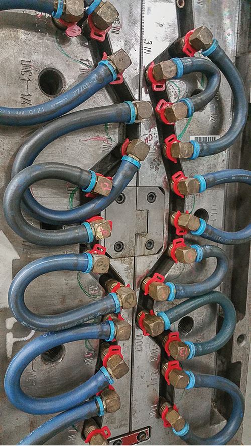
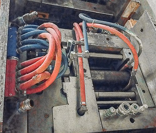
When it comes to cooling, some prefer water manifolds on the tool with just one main connection for the Ins and Outs to help minimize setup time. However, this arrangement has a slight disadvantage in maintenance: When working on the tool, the exterior water lines/hoses need to be removed and protected. In most cases, this is not a major ordeal, but I have had tools with numerous lines that required extra labor removing them and making sure they were installed back in the correct locations. It is very important to make sure the connections and the tool are labeled visibly to reduce the chance of cooling issues.
One other option some use for reducing the number of water connections is an internal flood system inside the tool with one main In and Out connection that eliminates the exterior hoses. The one drawback is not being able to verify whether a cross line has internal scale buildup or is restricted, when all the lines are connected to the same feed line. This typically requires tearing the tool down and removing all pipe plugs to evaluate the lines. With an external water manifold, you could have the same issue with a plugged line that goes undetected, but you have the ability to remove the hose or connection and verify the flow in each specific line.
Other molders choose to put manifolds on the molding machine rather than on the tool. This eliminates the exterior water-line hoses and keeps the tool “cleaner” for maintenance. I prefer this concept, but I am biased because I’m the one who is tasked with maintaining the tool.
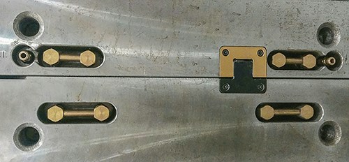
To reduce the number of connections, you can hard-plumb lines in series. It is best to have these recessed in the side of the mold to protect them. Many people will just add loops with hoses but these can add to the setup time and to the risk of water issues if not looped correctly. It is important to have a water diagram on the side of the mold to reduce this risk.
When designing water lines on the tool, you should try to have the connections on the sides or bottom of the mold and not on top of the mold. Yes, there are situations where water connections will need to be on the top, but do so only when absolutely necessary. I’m sure everyone reading this has experienced water leaks, which, if not cleaned up properly and quickly, can cause corrosion damage.
One issue I have witnessed many times is O-rings in the couplers going bad, causing small leaks that are not always noticeable. If the tool has the cavity inserted in a mold base with water on the top of the mold with pipe extensions, these small leaks can cause headaches for maintenance. The water runs along the pipe extension down to the cavity insert and will rust out the interior of the mold and inserts. This can produce some foul language in the tool room when trying to remove the cavity insert for maintenance. I also have had cases where the water had dripped out of the interior of the mold after the mold was pulled and ran into the cavity surface.
I am a fan of bubblers because they allow you to get water into tight areas where the typical water line or baffle will not fit. I always use high-flow tubes versus the brass tubes, because they allow for more GPM. But when using bubblers or other small water lines, it is critical to run these on their own circuit, or you will restrict the flow of the main water lines. I have seen this occur numerous times, causing a reduction of cooling efficiency.
After setup, it is important to verify the water flow to make sure everything is hooked up properly. And when connecting water lines to slides, it is important to make sure the slide was not bumped out of position, or you will cause damage or break a horn pin. This typically occurs when inadequate slide detents or retainers are used. I bring this up because have replaced many horn or guide pins for this reason.
EJECTORS, SLIDES & HOT RUNNERS
Protecting mold components is also important to reduce downtime and repairs. Rails or stand-off pillars should be used when plugs, switches, water lines, cylinders, etc. are protruding from the sides of the mold and cannot be recessed. Clamp plates can be extended beyond the mold base for protection as an option, as well. These options will protect your components when setting, pulling, transporting, and storing the mold.
The mold should also have the ejection designed with only as much stroke as is needed to remove the parts, runner, and gates. Excessive ejector stroke adds cycle time, extra mechanical friction, and excessive unsupported length of components, which can lead to wear and failures. (For more on this topic, see my February column.) You should also use only the amount of ejection pressure needed. Excessive pressure can cause damage from coining and can prevent you from noticing a failure before it’s too late.
When using tied-in K.O. rods, you should verify that they all are the exact same length and screwed in all the way. This sounds elementary, but I have seen this cause problems many times. For example, it can contribute to read-through issues on the plastic part. Also, use four ejector bars whenever possible to keep the ejector plate aligned. Using just two ejector bars on opposing corners can cause the plate to cock.
When the mold has suicide conditions, it can be beneficial to add springs, even when using tied-in K.O. rods, to prevent damage when pulling the mold. In some situations, the ejectors are run forward to unbolt the K.O. rods, and damage can occur if the plates are not all the way back. I have seen this occur numerous times over the years. When using spring return, the spring compression should never exceed the manufacturer’s specs. Again, this sounds elementary, but I have seen springs break because this advice was not followed. If you have a tool that has an issue with spring failure, you should verify that spring compression is within recommended limits or you will continue to have the same failures.
When using hydraulics for slides, ejection, or cores, try to keep them on the sides and bottom of the mold when possible. Hydraulic leaks can be very frustrating, and if the components are on top of the mold, you will have more of a headache with the oil running down into everything. The hydraulic connections should be labeled, or use different fittings for set and pull. A good option is to use male and female connections for the set and pull, respectively, to prevent improper setup. And when using multiple hydraulic sequences, you can use different size connections to prevent improper setup.
One other thing to consider is the location of hot-runner plugs or connections. I prefer to have them on the sides of the mold to prevent issues if there is a water leak. If the connectors are on the top of the mold you run the risk of getting water down inside the hot runner and drops, which can cause downtime and repairs with shorts or improper temperature readings.
One other issue with hot runners I have encountered over the years is with glass-filled Noryl PPE alloys. If this material is allowed to sit and bake over an extended period of time in the hot runner, it will solidify to the point where you will not be able to purge it out. This can cause extended downtime when you have to send the hot runner out for cleaning. I have not experienced this issue with any other material, but typically it is not a good idea to let any resin sit and bake in a hot runner for an extended period. I will get into some troubleshooting issues with hot runners later when I discuss repairs in the press.
In the next column, I will cover cleaning and maintenance in the press.
ABOUT THE AUTHOR
Related Content
Optimizing Pack & Hold Times for Hot-Runner & Valve-Gated Molds
Using scientific procedures will help you put an end to all that time-consuming trial and error. Part 1 of 2.
Read MoreValve-Gate Sequencer Controls Mold-Filling Sequence
PCS Company has introduced the Polimold Valve Gate sequencer to control the opening and closing of hot runner valve-gate pins.
Read MorePET Preform Hot Runner System Reduces Stack Height
Mold-Masters has cut the stack height of its PET-Series hot runner system from 300 mm to 260 mm, while maintaining a 3-plate design and the advantages therein.
Read MoreHot Runners: Truths. Myths, Overlooked Areas: Part 2
Here’s a view from the trenches of a tooling manager who, over 30 years, has experienced the joys and pains of using virtually every type of hot runner on the market. Part 2.
Read MoreRead Next
People 4.0 – How to Get Buy-In from Your Staff for Industry 4.0 Systems
Implementing a production monitoring system as the foundation of a ‘smart factory’ is about integrating people with new technology as much as it is about integrating machines and computers. Here are tips from a company that has gone through the process.
Read MoreBeyond Prototypes: 8 Ways the Plastics Industry Is Using 3D Printing
Plastics processors are finding applications for 3D printing around the plant and across the supply chain. Here are 8 examples to look for at NPE2024.
Read More
