Understanding the Influence of Screw Geometry on Melting Rate
They are not as closely connected as most processors think. Here’s why.
Polymer processing screws have been widely used for years but their performance is still a bit of a mystery to people who use them every day. For one thing, the melting rate is not as closely related to screw geometry as many would suspect. Rather it is more closely related to the peripheral velocity of the screw, the temperature of the barrel, and the polymer’s thermal and viscosity properties.
Tadmor, Klein and others in the 1950s developed a dimensionless relationship to describe the melting rate per unit of down-channel distance. In this equation, the higher the value of F, the higher the melting rate:
F={Vbx rm[Km(Tb-Tm)+( µ÷2 Vj2)] / 2[Cs(Tm-Ts)+l] }0.5
Simplified, this equation is the square root of the heat required for melting divided by the heat supplied by the screw rotation. Notice that there are no screw geometry terms showing in this equation; most of the terms are related to the polymer properties or the barrel temperature. The only unknown is the viscosity (µ), which changes throughout the screw. This requires an assumption for the average viscosity of the melt, which introduces a variable that is hard to quantify without a lot of experience and data.
Further explained, the melting rate for the screw is proportional to the square root of one half the velocity of the barrel relative to the screw plus one quarter the viscosity of the barrel times the viscosity in the film divided by the ratio of the heat transferred from the barrel to the film and the heat transferred from the film to the solid. The latter two are generally quite low due to the poor thermal conductivity of polymers.
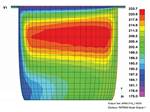
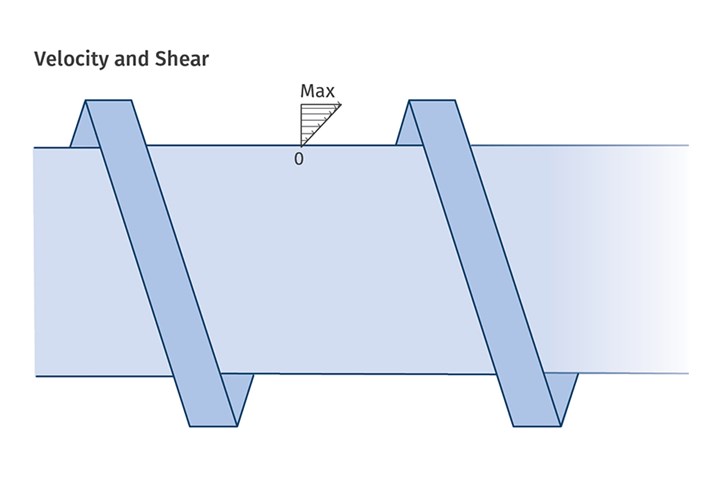 In a typical screw, the shear rate (melting rate) is maximum at the barrel wall and zero at the bottom of the channel. That’s why barrier screws and shear-type mixers reposition the unmelted solids for greater proximity to the barrel wall.
This means that the melting rate (F) is largely independent of the screw geometry for “plain” screws with no shear-type mixing sections or barrier flights. Those devices have been developed to enhance melting by simply redistributing the polymer in the channel to improve its proximity to the barrel. Essentially that is how barriers work. They reposition the melt from the channel to improve the proximity to the barrel wall for improved shear heating of the solids trapped in the continuously decreasing volume in the solids channel.
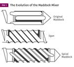
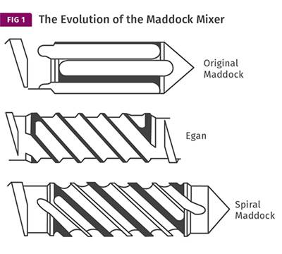
The same is true of “shear-type mixers” like the various configurations of the famous Maddock-style mixers where the solids are forced by geometry to a location near the barrel wall. Again, the closer the unmelted polymer can be relocated near the barrel wall, the greater the melting rate. The shear rate (melting rate) is maximum at the barrel wall and zero at the bottom of the channel (see illustration).
Poor thermal conductivity of polymers greatly reduces the magnitude of heat transferred to or from the barrel. Additionally, the temperature of the film at the barrel wall is generally near the barrel temperature, eliminating the temperature differential necessary for significant heat transfer. That means that most of the heat entering the film comes from the shear in the channel from the rotation of the screw.
If that weren’t true you could start your extruder up almost immediately upon turning on the barrel heat. Instead, it can take hours to reach a melt condition that will allow startup. This means that for simple flighted screws, higher melting rates require higher screw speed or longer melting sections.
Fortunately, improvements from the 1950s in various barrier designs and shear mixers that separate the melt and unmelt to selectively apply shear to the unmelt allow for more improvements in melting rates without greatly increased screw speeds or greater L/D. If you critically examine each of these devices, you will find each moves the unmelted polymer closer to the barrel wall to accomplish improved melting rates.
ABOUT THE AUTHOR: Jim Frankland is a mechanical engineer who has been involved in all types of extrusion processing for more than 50 years. He is now president of Frankland Plastics Consulting, LLC. Contact jim.frankland@comcast.net or (724)651-9196.
Related Content
The Effects of Stress on Polymers
Previously we have discussed the effects of temperature and time on the long-term behavior of polymers. Now let's take a look at stress.
Read MoreBack to Basics on Mold Venting (Part 1)
Here’s what you need to know to improve the quality of your parts and to protect your molds.
Read MoreImproving Twin-Screw Compounding of Reinforced Polyolefins
Compounders face a number of processing challenges when incorporating a high loading of low-bulk-density mineral filler into polyolefins. Here are some possible solutions.
Read MoreThree Key Decisions for an Optimal Ejection System
When determining the best ejection option for a tool, molders must consider the ejector’s surface area, location and style.
Read MoreRead Next
How to Compare Barrier Screws
When processors asked screw designer Robert Dray how to compare different types of barrier screws, he modeled melting capacity based on the biggest single factor, solids channel area. It gives a quick way to evaluate barrier-screw designs.
Read MoreEXTRUSION: Barrier Screws and Mixers
For some reason, there are a lot of barrier screws in operation with high-shear mixers, when a distributive mixer is usually a better choice.
Read MoreThe Role of Screw Design In Efficient Extrusion Of Medical Devices
For extruders of medical tubing, screw design plays a key role in maintaining dimensional control, physical properties, and more.
Read More
.jpg;width=70;height=70;mode=crop)
