
Optimize Feeding to Get More Money in Twin-Screw Compounding
Follow these practical examples to improve the feeding efficiency and productivity of your process.
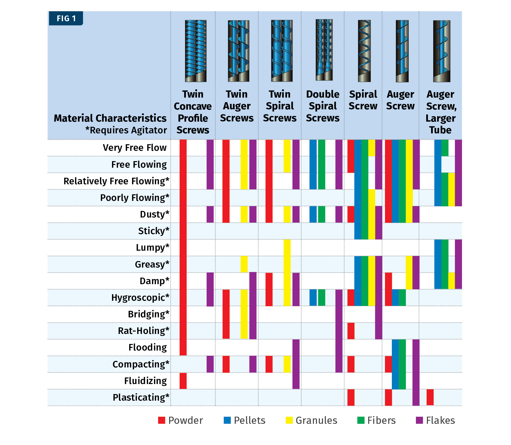
It’s vital to know the characteristics of the material in order to select the right feeder screw type. Here, a colored field in the table means essentially suitable.
With a profit margin of 20¢/kg, a 500 kg/hr increase in rate made possible by using FET could mean an increased profit of $600,000 annually, offsetting the cost of the unit several times over. At the same time, the specific energy requirements are reduced by 4% or 33 MWh annually.
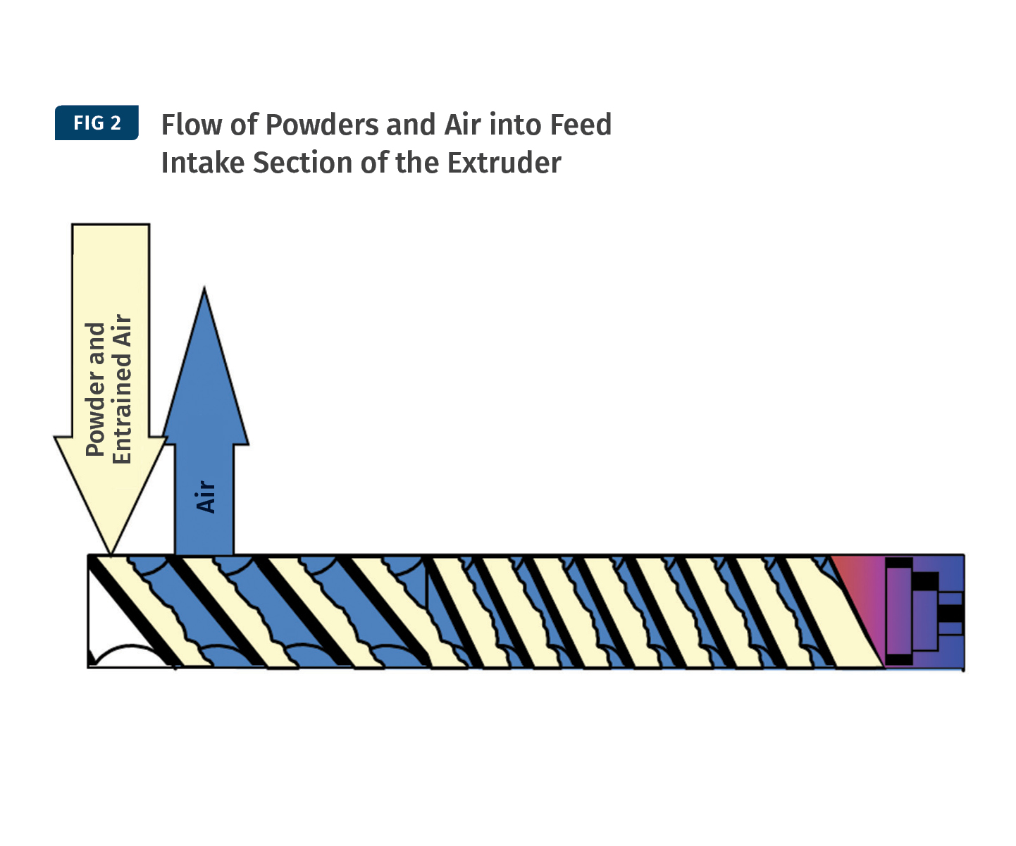
When feeding powders, air becomes entrained as the powders drop from the feeder into the extruder. Since the melt zone of the extruder is fully filled, the entrained air cannot move downstream past the melt seal with the molten polymer. Instead, it is forced to escape through the nearest upstream opening, which is usually the feed opening.
One way to reduce the amount of entrained air is to place the powder feeder on the same vertical level as the extruder, as close to the feed hopper as possible.
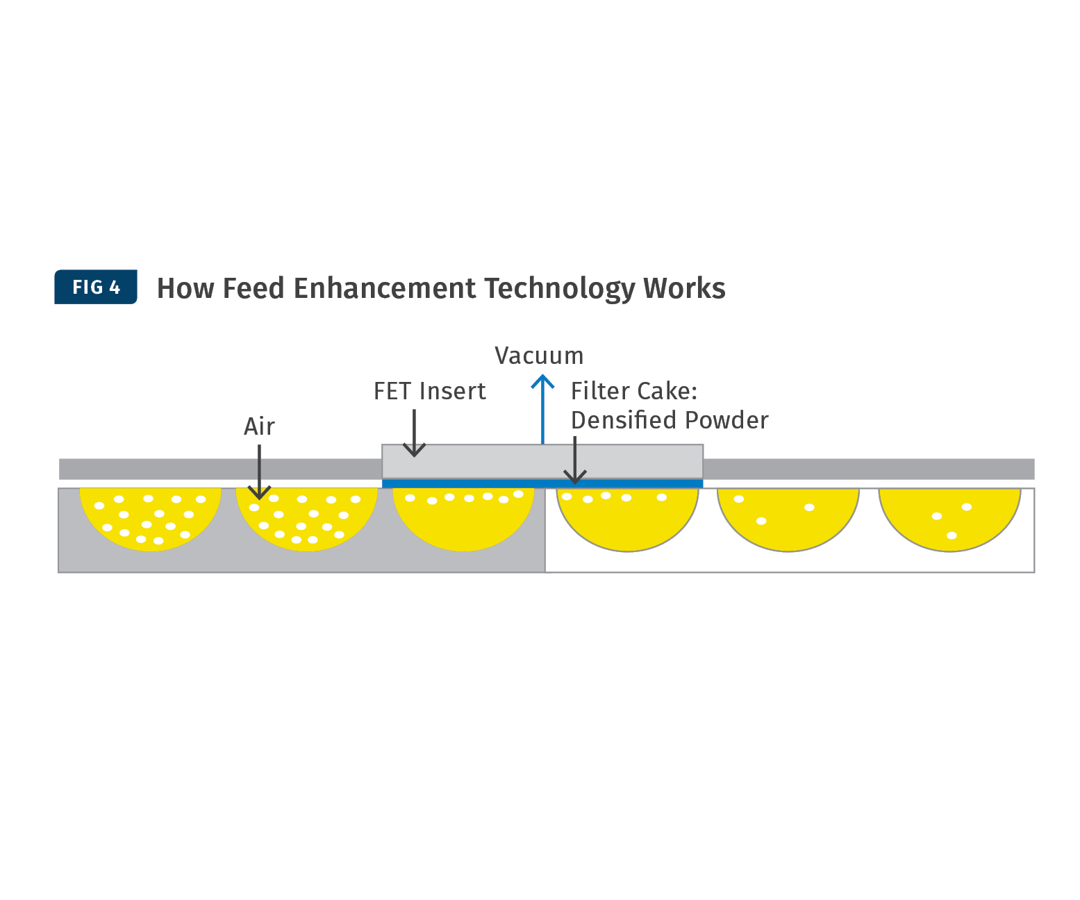
The FET insert is a porous, gas-permeable wall section, on which a vacuum is pulled externally. Drawing out the air surrounding the polymer increases the bulk density to improve feed rate.


Every business wants to increase profits. Companies can deploy many strategies to do so that can fall across various areas of the business, such as reducing inventory, negotiating lower prices from suppliers, or increasing marketing efforts, to name a few.
When it comes to operations, the capital equipment is often already in place and is therefore a sunk cost. Increasing profit- ability in this case usually depends on maximizing productivity of these assets. For twin-screw extrusion processes, this is most easily achieved by increasing throughput rate, thereby spreading operating costs (depreciation, labor, maintenance, etc.) over a greater amount of product produced in the same unit of time. Another option to reduce cost is by increasing energy efficiency in converting raw materials into finished goods. Since energy is relatively inexpensive in the U.S., the dollar amount of these savings tends to be minor compared with productivity increases. But there are other benefits businesses can realize by cutting energy consumption, such as reducing their carbon footprint and enhancing public image. In some cases, though, it is possible to achieve both increased productivity and reduced specific energy consumption.
When it comes to increasing throughput, first find out what is causing the current limitations. For twin-screw extrusion processes, limitations can exist anywhere from the feed system through the process section to the downstream equipment. For example, difficult-to-handle materials may stick or flow poorly through feeding equipment, limiting the rate at which they can be discharged into the twin-screw extruder. In the process section, an improperly designed melting section may not be able to fully melt the polymer above a certain throughput rate.
Conversely, materials with a high energy requirement to melt may be limited in rate by the amount of power that the motor and gearbox combination is able to supply. Limitations in the downstream equipment include high discharge pressure in the case of high-viscosity materials and restrictive dies, and high pellet temperature in the case of inadequately sized cooling equipment. Only once the limitation is understood can steps be taken to remove it. This process is one of continuous improvement, where if one limitation is removed, another will be uncovered at a higher throughput rate.
FEED SYSTEM
To achieve the highest throughput rates, feeding equipment must deliver an accu- rate and consistent feed to the extruder. To do this, the feed system must be designed according to the materials and throughput rates being fed (see Fig. 1). Easily fluidizing powders are handled well by a feeder with twin, narrow-pitch, con- cave augers, as the smaller clearances and longer path to the discharge abate the fluidization behavior. On the other hand, solid polymer pellets may become impinged in the tight clearances between these screws, so pellets benefit from being fed with a coarse-pitch, single auger. Other materials, such as wet or cohesive aggregates, tend to be best suited for a belt feeder rather than a screw feeder. Consult your feeder OEMs for their specific recommendations.
For materials that tend to bridge, rat hole, or stick to the hopper, agitation is needed to keep the product flowing consistently. Classically this has been done by some type of a mechanical stirrer. One downside of this method is that it can compact sticky materials, and increase the cleaning time when changing over to different materials. An alternative to mechanical stirring is the ActiFlow system, which works through an intelligent vibratory drive attached to the outside of the feed hopper. It continuously optimizes frequency and amplitude based on changing material flow conditions and provides feedback to the feeder controller to remove the vibratory noise from the load-cell signal.
In addition to selecting feeding equipment to best suit the mate- rials, take time to consider feeder control systems. One example is the automatic hopper-refill control. If the hopper is refilled too frequently, the controller spends less time measuring the loss in weight over time, which can reduce the accuracy of the feeder. On the other hand, if the level in the hopper is allowed to drop too low, the sudden pressure of material dropping into the hopper during a refill may cause a surge of material to slip through the screw, especially for low-bulk-density and easily fluidizing materials. When this surge of material falls into the extruder, it will cause a momentary increase in load on the motor, manifesting itself as an increase in torque on the extruder control screen. These torque spikes cannot exceed 100% of the extruder’s available torque or else safety interlocks will shut down the extruder to avoid an overload condition. As a result, the normal operating torque of the process must be kept lower to create room for these potential spikes.
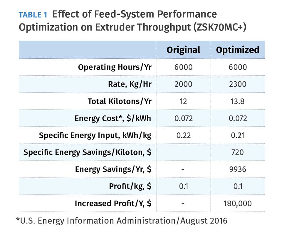
The increase in profitability with feed-system optimization can be calculated by the increased productivity. An example of his calculation is shown in Table 1 for a 70-mm twin-screw extruder processing a polyolefin masterbatch with a profit margin of 10¢/kg. In this example, a feeder that was experiencing surging during refill was replaced with one better suited for the material, allowing the throughput to be increased from 2000 kg/hr to 2300 kg/hr (4409 to 5070 lb/hr). This results in a possible $180,000 in additional annual profit, more than four times the cost of the new feeder. Additionally, since the degree of fill in the twin-screw extruder increases, specific mechanical energy input to the material decreases. This results in an energy savings of 5% or 138 MWh/yr
FEED INTAKE
After the feed system delivers material to the extruder, it must be conveyed downstream in the feed intake zone. A limit to the throughput rate occurs when the intake zone has insufficient capacity to convey the materials. The conveying capacity of the feed intake zone is determined by the free area of the twin screw and the pitch of the screw elements in this zone, along with screw speed and a few product-related parameters.
The free cross-sectional area of the extruder is fixed in a standard twin-screw extruder. Extruders with a larger outer-diameter to inner-diameter ratio will have more free area. It is important to consider this when procuring a new extruder. The product parameters are tied to the selection of raw materials. Changes are often complicated for purchasing or product- quality reasons.
Therefore, the parameters that can be optimized on an existing machine are the pitch of the screw elements and the screw speed. Increasing screw speed will typically result in a higher energy input to the material. This increase in energy can be partially offset by an increase in feed rate. However, this increase tends to trail off at increasing screw speeds. This results in a higher melt temperature, which among other downsides could cause issues in pelletizing or in product quality.
Increasing the pitch of the screw elements in the feed intake zone is the most innocuous change. As a rule of thumb, it is recommended to always start with the widest-pitch screw elements in the feed intake zone. Feed intake limitations can result when feeding powders, especially low-bulk-density or easily fluidizing ones, due to air becoming entrained as the powders drop from the feeder into the extruder.
In typical polymer processes, there is a melt zone comprised of a section of kneading blocks fully filled by polymer. Since this section of the extruder is fully filled, the entrained air cannot move down-stream past the melt seal with the molten polymer. In typical polymer processes, there is a melt zone comprised of a section of kneading blocks fully filled by polymer. Since this section of the extruder is fully filled, the entrained air cannot move downstream past the melt seal with the molten polymer. Instead, it is forced to escape through the nearest upstream opening, which is usually the feed opening (Fig. 2). As a result, there is a competing flow of the raw materials entering and the entrained air exiting.
One way to reduce the amount of entrained air is to place the powder feeder on the same vertical level as the extruder, as close to the feed hopper as possible. This minimizes the drop and reduces the amount of air that gets entrained.
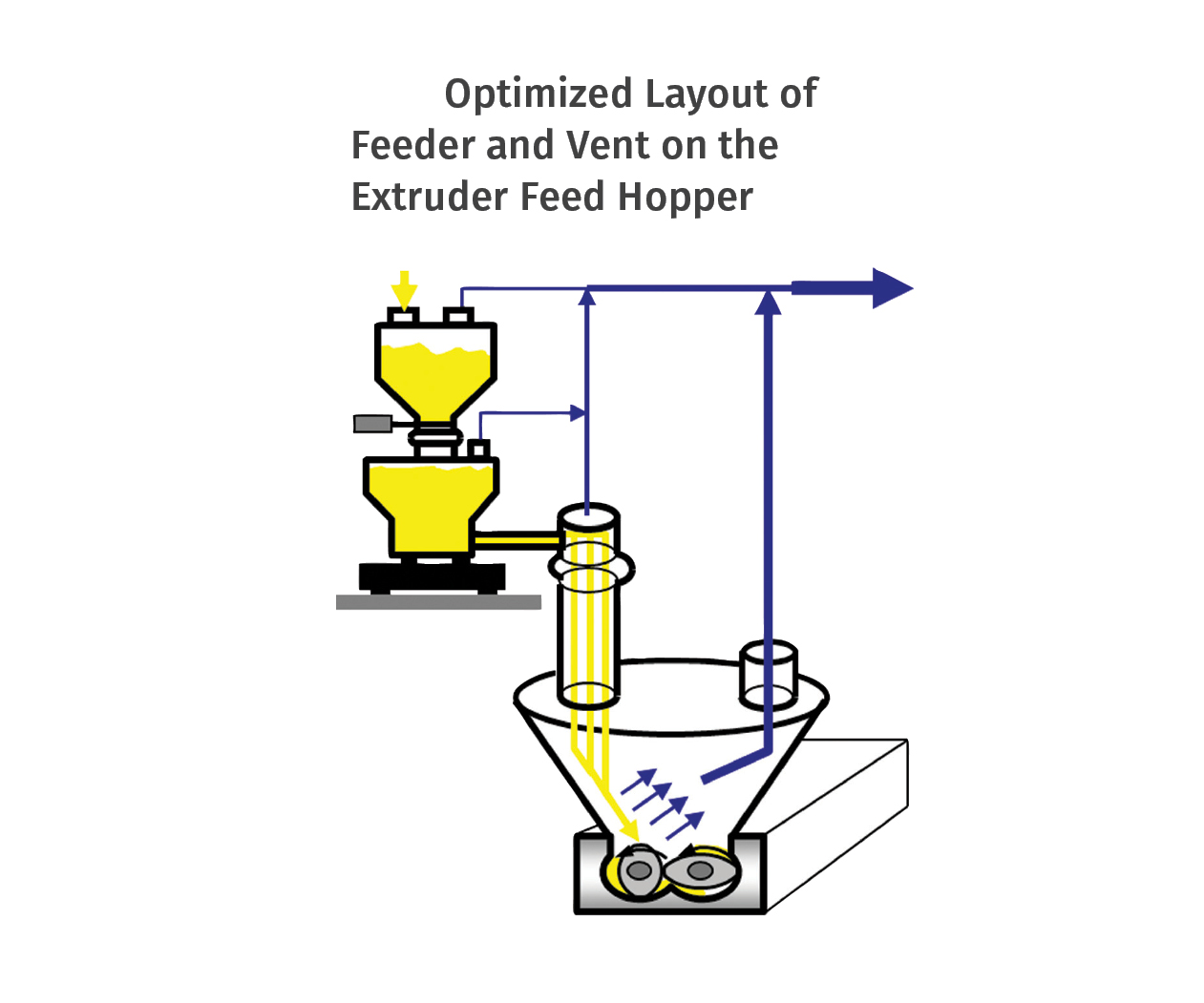
Another strategy is to design vents into the system to give the air alternate escape routes. A vent can be installed in the feed hopper itself. To increase the effect, the hopper should be designed so that the feeder discharges material down the side of the hopper on the same side as the down-turning screw in the twin-screw pair, with the vent stack on the other side of the hopper. This allows the air to flow away from the polymer on its way down to the extruder (Fig. 3).
The other location where a vent can be installed is in the twin- screw, upstream of the feed barrel. The entrained air is easily able to flow backwards in the twin-screw to the upstream vent barrel, while the solid powder is conveyed by the screws downstream.
These three strategies can be employed individually or in parallel with each other.
Another highly effective technique for getting powders into a twin-screw extruder is with the use of Feed Enhancement Technology (FET). In this technology (Fig. 4), a vacuum is applied through a porous filter in the barrel wall. Air is removed, while the powders are kept in the barrel. It works primarily by forming a cake of material on the barrel, increasing the coefficient of friction on the barrel wall. This increases the conveying efficiency. The secondary effect is to remove some of the entrained air from the powder, reducing its volume.
The magnitude of the effect of FET is not the same for all powders, and depends on attributes such as bulk density and particle size. For talc, it has been proven to increase throughput rate by over 250%, while for calcium carbonate, the increase in throughput is mostly negligible. The limitation is that FET can only be used in zones where only dry, unmelted powders are present. Wet or molten materials will plug the filter; and large, solid particles such as pellets will damage it. For compounding processes, this technology is typically applied to the side- feeder barrel, though it is also available in the main extruder barrels as well.
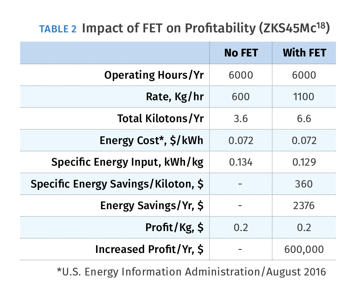
To calculate the profitability of installing FET, consider an example of a 45-mm twin-screw extruder compounding polypropylene with 40% talc for an automotive application (Table 2).
For this process, the throughput is limited by the volume of talc that can be fed. At rates higher than 600 kg/hr, the side feeder starts to back up, and the extruder is able to use only 54% of its total motor power. By installing FET, the conveying efficiency of the side feeder is greatly increased, and the throughput can be increased until the motor power becomes the limitation at same screw speed, the specific mechanical energy input to the material also decreases, and less power is used per kilogram of material. With a profit margin of 20¢/kg, the 500 kg/hr increase in rate could mean an increased profit of $600,000 annually, offsetting the cost of FET several times over. The specific energy requirements are reduced by 4% or 33 MWh annually.
The examples offered highlight just a few common limitations in feeding twin-screw extrusion processes. There are many more areas where limitations can occur. The principle of first identifying the limitation, understanding it, and implementing a solution, then repeating for the next limitation, can be applied for those limitations not discussed in this article. Factors such as energy cost, profit, and ability to sell excess production should be evaluated for your specific business. These calculations can provide the framework to justify taking on these optimization projects. As always, your twin-screw extruder manufacturer is a good first point of contact for process-optimization advice.
ABOUT THE AUTHOR: Alex Utracki is director of process technology for Coperion’s Compounding and Extrusion division. His group is responsible for trials in Coperion’s twin-screw extrusion process lab in Pitman, N.J. as well as providing technical support for process development, new machine sales, and existing customers. Contact: (856) 256-3019; alex.utracki@coperion.com; coperion.com.

Related Content

Safety, Recycling, and Compounding Trends Bring New Opportunity to 70-Year-Old Company
NPE2024: Vac-U-Max presents pneumatic conveying solutions for powdered materials.
Read More
Film Processor Automates Complex Resin Management, Blending & Distribution System
Polipak of Poland moves to BlendSave system to support sustainability and Industry 4.0 objectives.
Read More
Cost-Effective Single-Screw Feeder
New line of feeders said to be ideal for pellets, granules, and other free-flowing bulk materials.
Read More
Cut Loading Time Through Direct Charge Blending
Direct charge blender loading, a vacuum-powered automation process, can dramatically improve loading time and reduce material costs. In this article, we address ten common questions to help you determine if the systems are right for your facility.
Read MoreRead Next

Beyond Prototypes: 8 Ways the Plastics Industry Is Using 3D Printing
Plastics processors are finding applications for 3D printing around the plant and across the supply chain. Here are 8 examples to look for at NPE2024.
Read More
People 4.0 – How to Get Buy-In from Your Staff for Industry 4.0 Systems
Implementing a production monitoring system as the foundation of a ‘smart factory’ is about integrating people with new technology as much as it is about integrating machines and computers. Here are tips from a company that has gone through the process.
Read More
Recycling Partners Collaborate to Eliminate Production Scrap Waste at NPE2024
A collaboration between show organizer PLASTICS, recycler CPR and size reduction experts WEIMA and Conair will seek to recover and recycle 100% of the parts produced at the show.
Read More