A Guide to Single-Screw Mixers
To design the best mixers for single screws, you must completely understand how polymer moves through a mixer channel or groove.

Figure 1: This shows a single screw channel filled with melt with decreasing shear stress from the top sketch to the bottom sketch. This would be caused by either decreasing screw speed or decreasing polymer viscosity or both.
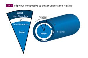
Several months ago, I wrote a column showing how melted polymer moves through the screw channels. Basically, it’s dragged by the rotation of the barrel surface relative to the screw. The screw flights simply determine the angle of flow with the barrel surface being the moving force. The polymer is completely stuck to all the screw and barrel surfaces, and does not slip or slide at all once melted. Rather, it is sheared or stretched.
If you were to remove the barrel, the polymer will simply rotate with the screw with no forward movement. The highest shear and velocity occurs at the barrel wall ( Vb) as it is the moving force in relation to the polymer and the lowest shear occurs at the bottom of the screw channel/groove (Vzero). There is zero shear stress (or no movement) on the screw channel walls as the polymer is assumed to rigidly stick to the walls and that can create “dead spots,” depending on the level of shear stress, shape of the channel/groove and the polymer viscosity. Figure 1 shows the lower shear stress in the corners radii of the screw channel.
This shows a single-screw channel filled with melt with decreasing shear stress from the top sketch to the bottom sketch. This scenario would be caused by either decreasing screw speed or decreasing polymer viscosity, or both. At very low screw speed or viscosity, it can be difficult to achieve even a semi-uniform melt flow condition throughout the channel.
Most mixing sections in single screws have similar flow characteristics as the screw channels, but are generally narrower, making them even more difficult to produce uniform melt flows. As a result, they depend on pressure from the preceding flights to match the output of the flighted sections. Consequently, unless they are greatly oversize, they almost always constitute a pressure drop in the screw.
The first set of mixer grooves illustrates a condition with a complete melt but mixing is still nonuniform because of the decline of the shear stress level as it moves away from the barrel wall and deeper in the channel. The deeper and narrower the channels, the poorer the mixing. A better design will have a feature that “rolls over” the mass in the channel from top to bottom so the entire melt sees the same or at least similar overall shear stress to become more uniform. This can be accomplished in a number of ways.
Interrupting the grooves in a screw channel and compensating the volume for the same flow and pressure drop can “rotate” the melt and provide a better overall mix.
Interestingly, one of the oldest and most widely used single-screw mixing sections does just that. It’s the Union Carbide or Maddock mixing section that Mark Spalding described in detail his recent column. It forces the polymer to transfer from one flute to another over a barrier rib to pass through the mixer, thereby assuring that the polymer in the bottom of the channels/grooves becomes mixed with the polymer nearer the tops of the channel/grooves. This can be done in other ways to get the same mixing levels without the high shear rib typical of the Union Carbide mixer, which aids in melting as well as mixing.

Figure 2: Adding a configuration to the mixer that “turns the melt over” will greatly improve uniformity.
However, many of the mixing devices I see (such as pin mixers, Dulmage styles and parallel peg styles in various configurations) are all confronted by the same issue wherein they apply all the shearing or mixing force from the same side. It seems likely that many designers believe that by simply repeatedly dividing the melt, they are mixing it. What they are missing is that the mixing force does not come from the screw but from the barrel.
Because shearing of a melt inherently decreases uniformly from the maximum at the barrel wall to the screw channel surfaces, it is essentially impossible to obtain a completely uniform mix without extreme length, which negatively affects temperature and many costs. By simply adding a configuration to the mixer that “turns the melt over,” uniformity can be greatly improved without these negatives (Figure 2).
For example, interrupting the grooves in a screw channel and compensating the volume for the same flow and pressure drop can “rotate” the melt and provide a better overall mix. Similar changes to many of the mixers used today would provide similar improvements in uniformity.
ABOUT THE AUTHOR: Jim Frankland is a mechanical engineer who has been involved in all types of extrusion processing for more than 45 years. He is now president of Frankland Plastics Consulting LLC. Contact jim.frankland@comcast.net or 724-651-9196.
Related Content
The Fundamentals of Polyethylene – Part 2: Density and Molecular Weight
PE properties can be adjusted either by changing the molecular weight or by altering the density. While this increases the possible combinations of properties, it also requires that the specification for the material be precise.
Read MoreUnderstanding Melting in Single-Screw Extruders
You can better visualize the melting process by “flipping” the observation point so the barrel appears to be turning clockwise around a stationary screw.
Read MoreThree Key Decisions for an Optimal Ejection System
When determining the best ejection option for a tool, molders must consider the ejector’s surface area, location and style.
Read MoreInjection Molding: Focus on these Seven Areas to Set a Preventive Maintenance Schedule
Performing fundamental maintenance inspections frequently assures press longevity and process stability. Here’s a checklist to help you stay on top of seven key systems.
Read MoreRead Next
For PLASTICS' CEO Seaholm, NPE to Shine Light on Sustainability Successes
With advocacy, communication and sustainability as three main pillars, Seaholm leads a trade association to NPE that ‘is more active today than we have ever been.’
Read MorePeople 4.0 – How to Get Buy-In from Your Staff for Industry 4.0 Systems
Implementing a production monitoring system as the foundation of a ‘smart factory’ is about integrating people with new technology as much as it is about integrating machines and computers. Here are tips from a company that has gone through the process.
Read MoreSee Recyclers Close the Loop on Trade Show Production Scrap at NPE2024
A collaboration between show organizer PLASTICS, recycler CPR and size reduction experts WEIMA and Conair recovered and recycled all production scrap at NPE2024.
Read More
.jpg;width=70;height=70;mode=crop)


