‘All-Purpose’ Screw for Injection Molding Handles a Wide Range of Polymers
A mixing section with replaceable dams is said to remedy the limitations of so-called “general-purpose” injection screws.
Unmelts, inconsistent viscosity, excessive shear heating, and streaks from uneven color mixing are some of the ills that critics attribute to the common “general-purpose” injection molding screw. Among those critics is Robert F. Dray, a well known screw designer with numerous patents to his name. He is fond of calling the typical injection screw a “no-purpose” screw that is “unable to process any polymer effectively.”
So it might sound like a contradiction now that his firm, R. Dray Mfg., Hamilton, Tex., is offering what it calls the APS, or “All Purpose Screw” (patent pending). The key to this screw is a mixing section with one or more removable dams that can be interchanged to alter the balance of distributive and dispersive mixing, depending on the viscosity of the material. The dams are keys inserted into slots and held by cap screws.
According to Dray, the mixing section makes up for the well-known problem of “solid-bed breakup,” which limits the ability of any non-barrier design to achieve complete melting, especially within the very short plasticating times and lengths of injection screws. A properly designed mixing section melts any solids that remain after the breakup of the solid bed. It also helps with color mixing and thermal homogenization of the melt. This can mean faster recovery times and ability to run at lower melt temperatures, resulting in less degradation, faster cycles, and energy savings, according to Dray. He notes that so-called Wave screws and other designs have been developed to improve melting, but they do not offer the same flexibility as the APS.
Dray, who founded Feed Screws Inc., now the screw division of Nordson Xaloy Inc., New Castle, Pa., believes injection screw design has been neglected and that it’s high time that injection molders benefited from the advances in screw design that have boosted quality and productivity for extrusion processors. He says that if the melt is prepared properly in the first place, there is less need for corrective measures, like in-cavity sensors and all sorts of process-control software routines, to compensate for melt-viscosity variations.
DAMS FOR HIGH & LOW VISCOSITY
When a customer orders an APS screw, the customer would provide the application requirements, including the range of polymers to be processed. The screw is then supplied with a set of easily removed dams of varying heights that sit in keyways. If the user is running a low-viscosity resin or one that is not shear-sensitive, and is experiencing color dispersion issues, for example, then one or more dams in the grooves of the mixing section is replaced with dams that provide less clearance. This would cause more flow to the land area of the mixer and thus greater dispersive mixing.
Conversely, if the user is running a high-viscosity polymer, shear-sensitive resin, or filled compound—where shear would be detrimental—then one or more dams on the lands of the mixer would be replaced with dams that provide less clearance. This would cause more flow to the groove, improving distributive mixing.
“Before now, the molder has only had backpressure as a tool to attempt to improve the performance of a conventional G-P screw,” Dray says. “While it may improve mixing and dispersion, raising backpressure comes at a cost—melt temperature is increased, causing greater energy consumption, potential thermal degradation, and longer cycles. Screw-recovery time is also increased, which can contribute further to increased cycle times.”
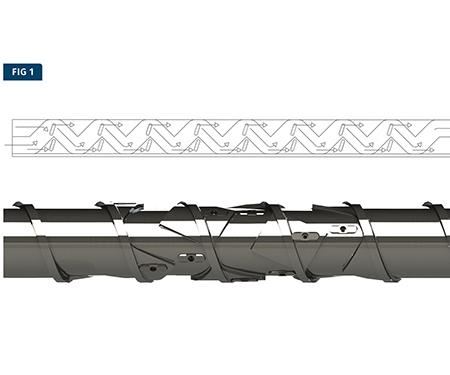
Now there’s an alternative—or two, actually. Dray offers two versions of the APS and is continuing testing to determine whether they perform differently. One version (Fig. 1) induces flow from the transition section into the groove of the mixer as well as over the land. The two flows converge and then continue in the groove and over the land on the forwarding side of the channel. This is repeated throughout the mixing section, as the arrows in the figure describe.
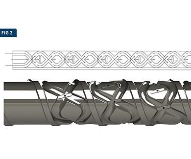
The second version (Fig. 2) induces flow from the trailing side and the forwarding side of the channel into the grooves. Flow also proceeds over the entry land. As these three flows proceed downstream, they converge. This is repeated throughout the mixing section. Dray notes that the APS is also applicable to extrusion—specifically to satellite extruders on coextrusion lines, which are often utilized to run a variety of different resins.
“For the first time,” Dray says, “molders and extruders have a screw design that can be modified at the site by removing the screw far enough to expose the removable dams and then replacing the dams as required. In this way, any change in polymer, regrind percentage, or only changes to improve operating conditions can be accommodated on-site.” Dray adds that molders could save money by modifying existing G-P screws through machining or “recutting” to convert them to an APS design.
Related Content
Understanding the Effect of Pressure Losses on Injection Molded Parts
The compressibility of plastics as a class of materials means the pressure punched into the machine control and the pressure the melt experiences at the end of fill within the mold will be very different. What does this difference mean for process consistency and part quality?
Read MoreInjection Molding: Focus on these Seven Areas to Set a Preventive Maintenance Schedule
Performing fundamental maintenance inspections frequently assures press longevity and process stability. Here’s a checklist to help you stay on top of seven key systems.
Read MoreIs There a More Accurate Means to Calculate Tonnage?
Molders have long used the projected area of the parts and runner to guesstimate how much tonnage is required to mold a part without flash, but there’s a more precise methodology.
Read MoreGot Streaks or Black Specs? Here’s How to Find and Fix Them
Determining the source of streaking or contamination in your molded parts is a critical step in perfecting your purging procedures ultimately saving you time and money.
Read MoreRead Next
Making the Circular Economy a Reality
Driven by brand owner demands and new worldwide legislation, the entire supply chain is working toward the shift to circularity, with some evidence the circular economy has already begun.
Read MoreBeyond Prototypes: 8 Ways the Plastics Industry Is Using 3D Printing
Plastics processors are finding applications for 3D printing around the plant and across the supply chain. Here are 8 examples to look for at NPE2024.
Read More

