How to Stop Flash
Flashing of a part can occur for several reasons—from variations in the process or material to tooling trouble.
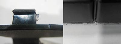
Flashing of a part can occur for several reasons—from variations in the process or material to tooling trouble. Flash appears on the part's edge along the parting line of the mold or anyplace where the mold has metal meeting metal to form a boundary of the part.
More often than not, the tool is the culprit, so recognizing what type of flash you are getting and when it is occurring can point you in the right direction.
Check Out the Tool
A common first response to reduce flash is to slow down the injection rate. While decreasing the injection rate eliminates flash by raising material viscosity, it also increases cycle time and still doesn't address the original cause of flashing. Worse yet, flash may reappear during the pack/hold phase.
Flash can occur during filling (first injection stage) or during the pack/hold (second stage), and it can occur with conventional parts and with thin-walled parts. Discovering in which stage flash occurs helps to reduce the complexity of determining the cause. A simple test is to bring the second-stage (pack/hold) pressure to the minimum the machine allows, which should be below 500 psi plastic pressure. The aim is to see the effect of just barely filling the cavity. First-stage injection fills 92% to 99.9% of the part, but this stage must end before the cavity is full. At the minimal pressure level for the second phase it is easy to inspect whether the part is a short shot at the end of first-stage injection. If there is flash on the short shot, we can focus on parameters affecting first-stage injection. If you don't get a short shot at all, then the answer may be to adjust the transfer point to avoid over-filling the cavity.
Proper mold cleaning may be the solution to flashing.
Keep in mind that with thin-wall parts, even short shots can generate enough pressure to blow the clamp open. But if you see flash in a part with an "average" wall thickness after a short shot of the first stage, the most likely cause is a parting-line mismatch in the tool. Clean off any plastic, dirt, or contaminants that could keep the mold from closing properly. Check the mold especially for bits of plastic behind slides and down in the pocket of the leader pins. After such housekeeping, if flash persists, check for parting-line mismatch with pressure-sensitive paper, which can reveal if the mold is clamping evenly along the parting line. A suitable pressure-sensitive paper will have a rating of 1400 to 7000 psi or 7000 to 18,000 psi.
In multi-cavity or family molds, flash is often caused by an improper balance of melt flow. If filling of the cavities is not uniform, the packing is not uniform. This is why multi-cavity molds may see flash in one cavity and sink marks in another during the same shot. Though not the subject of this article, there are established procedures for determining mold balance. (One such procedure is the "5 Step Process" from Beaumont Technologies, Erie, Pa.)
Inadequate mold support can also lead to flash. Molders should consider whether the machine has enough support pillars in the right places for the cavity and core plates.
The sprue bushing is another possible source of flashing. Nozzle contact forces can range from 5 to 15 tons. If thermal expansion causes the bushing to "grow" far enough past the parting line, the nozzle contact force can be enough to push on the moving side of the mold, trying to open it. For non-sprue-gated parts, molders should check the length of the sprue bushing while it is hot.
| FLASH: CAUSES & REMEDIES | |
| Possible Causes | Possible Remedies |
| Parting line mismatch or mold damage | Clean mold surfaces and behind slides and inspect cavity for any obstruction to proper clamping. Also check for a clamp misalignment, tool damage, uneven tiebar stretch, or improper machine leveling. Use pressure-sensitive paper to check pressure on parting line in flash area and non flash area while the tool is in the press. |
| Mold improperly supported | Check number, placement, and length of support pillars in mold. |
| Uneven flow in a multi-cavity tool | Use Beaumont "5 Step Process" to check mold balance. |
| Clamp tonnage too low | Reduce pack/hold pressure. Use a press with higher clamp force. |
| Clamp pressure too high | Reduce clamp tonnage. |
| Sprue bushing too long | For non-sprue-gated parts, check thermal expansion of sprue bushing under production conditions. Shorter bushing may be needed. |
| Overfilling cavity during first-stage injection | Adjust first-stage cut-off position or reduce shot size. Also check machine response on switchover from filling to pack/hold stage. |
| Viscosity too low | Test melt temperature to confirm it is not above supplier's recommended limit. Check melt flow rate before and after molding for signs of degradation. Minimize melt residence time. If resin is hygroscopic, check moisture content. Try different lot of resin. Only as a last resort, reduce injection rate. |
Clamp Concerns
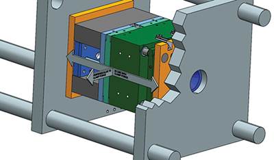
Next, let's examine clamping. If the flash is concentrated toward the center of the mold, it could be caused by too high a clamp pressure. If a small mold is mounted on a large platen, the forces on the mold can be greater on the four outside corners than in the center. The excessive clamp pressure may tend to "wrap" the platens around the mold. To solve the problem be sure that the mold takes up about 70% of the distance between the tiebars.
Flash can also be caused by too little clamp tonnage. If the part passes the first-stage short-shot test without flash, then the pack/hold phase may be pushing the parting line apart. Increasing the clamp tonnage may be the solution. That's especially true of high-speed filling in a thin-wall application, which can require 35,000 to 60,000 psi plastic pressure in the nozzle.
Clamp misalignment can cause flash. It can be due to the machine not being level—which is easily checked and remedied. Checking for lack of clamp parallelism, which can also produce flash, takes more work. Low-cost solutions include use of a standard square fixture and measuring tiebar stretch (which should not vary by more than 0.002 in.). A better but more expensive route is to use the newer laser method for checking parallelism.
Process-Related Problems
If material viscosity is too low, flashing can be the result. Resin can become too "runny" for a variety of reasons: too high a melt temperature, excessive residence time that causes degradation, presence of moisture from improper drying (which also degrades some resins), or an excessive amount of colorant that contains a lubricating vehicle. You can take the temperature of the melt at the nozzle with a hot probe or an infrared sensor. Checking the melt-flow rate before and after molding may indicate whether material degradation is the cause. A 30% change in melt flow rate is acceptable for unfilled resins, while a change of 40% or more is not. However, a melt-flow increase of 40% or more may be acceptable for filled resins. Instruments are also available to check moisture content of the resin. If none of these are the problem, you can switch to a higher-viscosity resin, but that may change performance properties as well.
ABOUT THE AUTHOR: John Bozzelli has taught seminars on plastics design and processing for more than 15 years. He has extensive experience in polymer development and processing from more than 20 years with Dow Plastics. He holds 10 patents and has written more than 60 papers covering plastics, processing, and machine specifications. He is the founder of Injection Molding Solutions/Scientific Molding in Midland, Mich., a provider of training and consulting services to injection molders. Contact: john@scientificmolding.com; (989) 832-2424,
Related Content
Fundamentals of Polyethylene – Part 6: PE Performance
Don’t assume you know everything there is to know about PE because it’s been around so long. Here is yet another example of how the performance of PE is influenced by molecular weight and density.
Read MoreThe Importance of Melt & Mold Temperature
Molders should realize how significantly process conditions can influence the final properties of the part.
Read MoreThe Effects of Time on Polymers
Last month we briefly discussed the influence of temperature on the mechanical properties of polymers and reviewed some of the structural considerations that govern these effects.
Read MoreHow to Select the Right Tool Steel for Mold Cavities
With cavity steel or alloy selection there are many variables that can dictate the best option.
Read MoreRead Next
TOOLING: Flash-Free Molding: Part Two
Parting-line maintenance, mold spotting, and machine conditions can all contribute to flash.
Read MoreTOOLING: Flash-Free Molding: Part 1
A robust process window relies a lot on tooling. So it stands to reason that making a tool change to address issues provides a more robust solution
Read MoreFor PLASTICS' CEO Seaholm, NPE to Shine Light on Sustainability Successes
With advocacy, communication and sustainability as three main pillars, Seaholm leads a trade association to NPE that ‘is more active today than we have ever been.’
Read More
.jpg;width=70;height=70;mode=crop)


