TOOLING: Flash-Free Molding: Part Two
Parting-line maintenance, mold spotting, and machine conditions can all contribute to flash.
Last month, in Part 1 of this series (see Editors' Picks top right), I said flash is avoidable if three conditions are met, no matter what process or material is being used:
• Clamp pressure must exceed
cavity pressure.
• The tool must be robust enough to prevent deflection both in-line with clamp force and perpendicular to clamp force.
• All shutoffs or parting lines must be “true net,” meaning they are tight with no gaps, damage, or anything holding the mold open.
Part 1 dealt with the first two conditions. In this article, we will get into issues of tool design concerning shut-offs and parting-line maintenance, and also where the machine itself can contribute to flash.
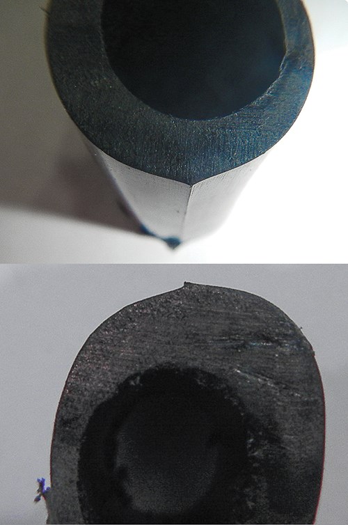
First, I would like to briefly go over how to define flash. Flash can be misdiagnosed at times, such as in the case of mismatched parting lines or rolled parting-line edges. True flash can be seen or felt from both sides, while the result of parting-line mismatch will only be seen or felt from one side. Rolled parting-line edges, typically a result of benching/polishing the cavities, can at times be diagnosed as flash and can also be felt from both directions. In a future column, I will get into the repair side to address these issues.
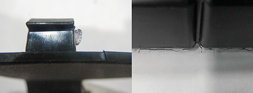
But mismatched and rolled parting lines are not issues that fall under the “three rules of flash” because they are not true flash. So-called “feather flash” is another form of flash but is typically easy to diagnose. Feather flash is little strings of plastic along the edge of a part on the main parting line. The root cause of this is lack of clamp force and the clamp blowing open under injection pressure, allowing the plastic to flow between the shut-offs, causing the little strings of plastic.
On the tooling side, I have seen many times where shut-off draft angles contribute to flash. Typically it is from wear, with the shut-off angle being too close to vertical. It is best to keep your shut-off angles at 5° or greater, but sometimes the part design does not allow this.
If this is the case, parting-line locks or lock angles become a necessity. The leader pins and bushing cannot be relied on to protect the shut-offs. I personally am a fan of zero-draft side locks. In any case, the draft angle of the lock angle or parting-line lock needs to be less than the draft of the shut-off to be able to protect it from wear. Tapered parting-line locks are great for controlling mismatch situations but do not protect shut-offs with draft angles less than the taper.
It is also critical, especially on large tools, that the water temperatures are the same on both the cavity and core to protect the shut-offs. Thermal expansion from running the two halves at different temperatures can contribute to wearing out the shut-offs and causing flash. I know there are many times where water temperatures are used on one half to address part-quality issues or sticking issues, but I want to point out the disadvantage in that worn shut-offs can become an issue.
I also want to bring up how improperly spotting the tool during the build process can contribute to wear issues, causing flash. I’ve been hands-on in molding for 26 years, and in dealing with tooling maintenance for the past 12+ years, and I have found this to be an issue at times. Every tool maker has its own interpretation of how to spot a tool. If the shut-offs are spotted where they are hitting too hard on low-draft shut-off angles, you are at high risk for wear or galling. Even on the repair side, when spotting after a weld, the weld should not hit harder than the existing parting lines.
Another area that can contribute to flash is inadequate parting-line maintenance. The parting lines should be kept clean and free from buildup and debris. Flaking from subgates, cashew gates, runner systems, and ejector pins can cause parting-line damage and contribute to flash. Any issues with flaking should be addressed and eliminated. This is a subject I will address in a future article, along with why flash at runner boss pins can be acceptable.
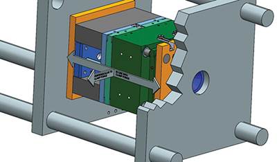
The machine can also contribute to flash issues. If the platens are not clamping up parallel to each other, you will have uneven clamp force transmitted to the mold. To diagnose this condition, the mold could be rotated 180° to see if the flash changes position. If platen parallelism is a concern, the tiebars should be checked with a strain gauge to verify they have equal strain. The machine should also be checked for leveling during this procedure.
The size of the mold relative to the platen surface area can also contribute to flash. Running an undersized mold in a press can cause platen distortion, leading to uneven clamp force on the mold. Note that flash from this cause will typically show up near the center of the mold, where the platen distortion is at the maximum.
A similar issue is with any tool that has an offset sprue or hot runner and is mounted off-center on the platen. The flash in this case will typically be in the area farthest from the center of the platen. A solution to both of these issues is to add support with stand-off rails on the mold that equal its stack height. Or, extend the clamp plates out and add support pillars outside of the mold.
At times the machine may not achieve the desired clamp force. If there is a hydraulic leak, a press may not reach full clamp force, or after reaching the desired clamp force the leakage causes the force to bleed down. Also verify that the machine doesn’t have a setting that allows the clamp pressure to drop early in the cycle. Machines can also decompress the clamp at the end of pack/hold to allow for quicker clamp opening. Some controllers allow you to let the clamp pressure drop earlier in the cycle even prior to peak cavity pressure.
Dial indicators and other devices can be used to help diagnose whether the clamp is blowing open. If you are detecting clamp movement, this will help focus troubleshooting on the machine rather than blaming the mold.
The ideal situation is to have uniform clamp force over the entire surface of the mold to overcome the cavity pressure developed during processing, as well as having a tool that is robust enough to prevent deflection and is designed to reduce wear.
Related Content
Why Shoulder Bolts Are Too Important to Ignore (Part 1)
These humble but essential fasteners used in injection molds are known by various names and used for a number of purposes.
Read MoreFundamentals of Polyethylene – Part 6: PE Performance
Don’t assume you know everything there is to know about PE because it’s been around so long. Here is yet another example of how the performance of PE is influenced by molecular weight and density.
Read MoreThe Effects of Time on Polymers
Last month we briefly discussed the influence of temperature on the mechanical properties of polymers and reviewed some of the structural considerations that govern these effects.
Read MoreBack to Basics on Mold Venting (Part 1)
Here’s what you need to know to improve the quality of your parts and to protect your molds.
Read MoreRead Next
TOOLING: Flash-Free Molding: Part 1
A robust process window relies a lot on tooling. So it stands to reason that making a tool change to address issues provides a more robust solution
Read MoreMaking the Circular Economy a Reality
Driven by brand owner demands and new worldwide legislation, the entire supply chain is working toward the shift to circularity, with some evidence the circular economy has already begun.
Read MoreBeyond Prototypes: 8 Ways the Plastics Industry Is Using 3D Printing
Plastics processors are finding applications for 3D printing around the plant and across the supply chain. Here are 8 examples to look for at NPE2024.
Read More
