Why Shoulder Bolts Are Too Important to Ignore (Part 1)
These humble but essential fasteners used in injection molds are known by various names and used for a number of purposes.
I especially enjoy writing articles on subjects that are important to our industry but are rarely given the attention they deserve. Maybe it’s because these topics are not often, if ever, discussed in schools, training seminars, or SPE functions. This month’s article on shoulder bolts is a good example of an important subject on which very little information is readily available. There is so much to know about this common fastener and how it directly affects the performance and longevity of your molds.
What are Shoulder Bolts?
Shoulder bolts are used in in a variety of ways and for various purposes. Their two primary functions in injection molds are limiting the distance a plate travels and pulling a plate during mold opening. Shoulder bolts are frequently used in three-plate molds and stripper-plate molds. While the generic name of this type of fastener is shoulder bolt or shoulder screw, these applications have inspired other, often more common names, such as range bolts and stripper bolts, based on their function.
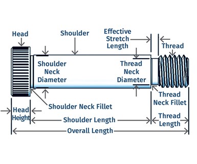
As seen in the accompanying diagram, shoulder bolts have three main sections: the head, the shoulder, and the thread. You specify a shoulder bolt by its shoulder diameter and shoulder length. For example, a ⅜ × 2 shoulder bolt has a shoulder diameter of ⅜ in. and a shoulder length of 2 in. If you purchase this ⅜-in. bolt from a mold-component supplier, the thread will be ⅚-18 UNC, not ⅜-16 UNC. The overall length of a shoulder bolt is the height of the head, plus the length of the shoulder, plus the length of the threaded portion. This nomenclature is very different from that of a standard bolt.
Shoulder bolts are available in both standard and precision grades. The diameter of the shoulder of a standard shoulder bolt is typically 0.002 to 0.004 in. smaller than its nominal value. Precision-grade shoulder bolts are only 0.001 or 0.002 in. smaller. Precision-grade shoulder bolts are typically used in applications where the shoulder acts as a shaft for a sliding or rotating component, such as a bushing or bearing. In these instances, the shoulder is referred to as a journal.
Tolerance and Torque
The tolerance on the length of the shoulder is typically ±0.005 in. However, some suppliers have length variation as much as 0.020 in. Several mold-component suppliers don’t even specify this tolerance. That can be a major problem. If the length of the shoulders varies by a significant amount, any plate in contact with the bolts can cock and possibly bind. The more likely scenario is that the head of the shortest bolt will break prematurely due to uneven load. Therefore, it is incumbent on the toolmaker to measure the shoulders and possibly machine them to a uniform length.
Most manufacturers include a slight reduction in diameter directly under the head. This is called the shoulder neck. It allows the head of the bolt to seat flush against its mating surface. Most manufacturers add a radius between the shoulder and the head of the bolt to reduce the notch effect. If the bolt has a radius, make sure that any washer or mating surface clears the protrusion. Otherwise, the load applied to the head of the bolt will be concentrated over a very small area and can cause the head to crack.
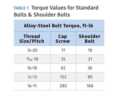
All manufacturers include a slight reduction in diameter at the end of the threads where they meet the shoulder. This is called the thread neck. It is necessary for manufacturing and lets the shoulder seat flush against its mating component. The thread neck is the weakest point of a shoulder bolt because it has the smallest diameter. This is why the torque values for shoulder bolts are about 40% less than the torque values for standard bolts with the same thread size and pitch, as shown in Table 1. If a shoulder bolt is over-torqued, it will most likely fracture at this location.
The thread neck is the weakest point of a shoulder bolt
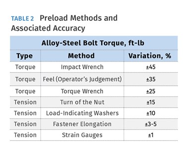
Properly torquing a shoulder bolt is very important. When you torque a bolt, it stretches like a spring. This spring-like tension reduces the chances of a bolt coming lose due to external forces such as impact and vibration. The amount a bolt will stretch is directly related to its “effective length.” For the sake of simplicity, the effective length of a shoulder bolt is the distance between the face of the shoulder and the closest engaged thread, as shown in the diagram. As you can see, shoulder bolts have a very short effective length. They will not stretch very much, and therefore will not have a lot of holding force. That is why shoulder bolts have the nasty habit of coming lose. The chance of one coming lose when affixed to a heat-treated component is even greater. Using a thread-locking compound can help, but properly torquing the bolt is best. So, what is the best way to torque a bolt? Table 2 lists various methods used to torque or preload bolts and the accuracy of each method.
It probably comes as no surprise that the torque accuracy of someone going by feel is very poor, but you would think that using a torque wrench would be very accurate. The reason why the torque wrench variation is as much as ±25% is due primarily to the coefficient of friction. The torque applied to a fastener must overcome frictional forces before any preloading takes place. If the assembly is not clean and lubricated, there is a considerable amount of friction at two locations—the bearing surface under the head (or in the case of shoulder bolts, the shoulder), and the thread-to-thread contact surfaces. Approximately 50% of the torque applied to a bolt is used to overcome the head-bearing friction, and about 35% is used to overcome the thread-contact friction. Therefore, 85% of the torque value is used strictly to overcome friction and only 15% is used to preload the bolt. The error percentages in Table 2 apply just to that 15%. If these two frictional surfaces are lubricated with cadmium plate, molybdenum disulfide, anti-seize compounds, etc., the friction is reduced by roughly 10% and thus, a substantially greater preload is obtained with the same amount of torque.
Always clean and lubricate the bearing surfaces of a bolt.
Therefore, always lubricate the threads of any bolt during assembly, as well as under the head or shoulder. Interestingly, the friction factor is at its highest value the first time you torque a new bolt. It gradually lessens with each subsequent loosening and tightening.
The turn-of-the-nut method for torquing a bolt can be as simple as rotating the bolt, or nut, by ⅓, ½ or ⅔ of a revolution past snug. Snug is defined as the point where you can no longer loosen the bolt by hand. The amount of revolution is based in part on the effective length of the bolt. However, since there are so many variables with this method, it should be considered a rule of thumb.
There are companies that offer sophisticated equipment to measure the tension, not the torque, on a bolt, but they are fairly expensive and thus overkill for moldmakers. There are also mathematical calculations, which are very accurate, if you have a degree in engineering and nothing else to do with your time. In critical applications, you might consider using a load-indicating washer. There are several different types of these washers on the market. They are commonly known as DTI’s, or Direct Tension Indicators. They are not very expensive, very easy to use, and as Table 2 shows, extremely accurate.
Materials and Thread
The industry-standard shoulder bolt in the U.S. is made of medium-carbon-alloy steel, heat treated, quenched and tempered to 32-43 Rockwell C (as per ASTM A574), with Class 3A UNRC (Unified National Rolled Coarse) thread and a minimum tensile strength of 160,000 psi, which meets ANSI/ASME B18.3 specifications. Yes, that’s a mouthful, but if you are ordering bolts from a general supply company, be very careful that they meet these specifications.
The “R” in UNRC indicates the bolt was made using the rolling process, which dramatically increases its fatigue life. The “A” in class 3A means that it’s an external thread. If it was a “B” it would mean an internal thread, like for a nut.
The “3” in class 3A describes the fit of the thread. For UNRC external threads there are three standard classes of fit: 1A, 2A, and 3A. At one time, there was a class 4 thread, but it is now obsolete. There is also a class 5 thread, but this has an interference fit. Thread classes 1 through 3 are “clearance” fits. That is, they assemble without interference. The higher the class number, the tighter the fit. Class 1 threads have an extremely loose fit, with an intentionally significant amount of play. This class is used for quick and easy assembly and disassembly. Threaded rod or “all-thread” is an example of this class of thread. A Class 2 thread has the best balance in terms of performance and economy. It has enough clearance to minimize any galling or seizing, and sufficient clearance for lubricants, thread-locking compounds, platings and coatings. Nearly 90% of all commercial fasteners are this class of thread.
Moldmakers don’t use “commercial” fasteners. We use class 3 threads, which are for close-tolerance applications, where safety is a design consideration. This fit class has only a little clearance for lubricants or thread-locking compounds. That is why sometimes a bolt may be a little difficult to install, and you might think your tap has worn out.
Has anyone ever given any thought to the strength of the thread on a shoulder bolt? Why would you?
The length of the threaded section is a fixed value. You get what you get, but that’s OK because screw manufacturers use the correct thread length to achieve the maximum holding power. However, there are times when you have to make a custom shoulder bolt in order to satisfy a problem when a standard size is not available—typically when a very long shoulder is needed. That’s when knowing some additional information about thread strength is important.
Ideally, you want the bolt to break in tension before it strips the threads. This depends on two things: the strength of the material that the bolt is screwed into, and the amount of thread engagement. If the strength of the steel into which the shoulder bolt is screwed into is greater than the strength of the steel of the bolt, and there is sufficient thread engagement, the bolt will not strip the threads. It will undergo tensile failure first. But what if you have a mold with a shoulder bolt screwed into mild steel or aluminum? It’s not going to take a lot of force to strip those threads out, no matter what the thread engagement length is. In a case like this, try to install a hardened nut or threaded bushing that is retained in the back of the plate.
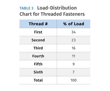
Next, what is the minimum amount of thread engagement required to prevent a bolt from stripping? There is a rule of thumb that says the amount of thread engagement for a bolt should be 1 to 1.5 times its nominal diameter. You should know by know how I feel about rules of thumb. There are some mathematical formulas available to calculate the optimal amount of thread engagement, but there is a much easier way that is sufficiently accurate. Table 3 breaks down the load distribution over the first six threads of a carbon-steel threaded fastener. As you can see, the first six threads account for 100% of the holding power. If you simply divide the number 6 by the pitch of the fastener, you get the minimum required thread-engagement length. For example, for a ¼-20 bolt:
in. of engagement.
The first six threads of a fastener account for 100% of its holding power
While this value is correct for the amount of thread engagement, it does not account for the lead-in on the tip of the thread, nor does it account for the runout, or thread neck. These two areas account for about another three threads. Therefore, to calculate the overall distance from the end of the shoulder to the tip of the thread, use 9, instead of 6, divided by the pitch. If you check a supplier’s catalog, you will see that the overall thread length that comes with standard shoulder bolts is very close to 9 divided by the pitch.
About the Author
Jim Fattori is a third-generation injection molder with more than 45 years of molding experience. He is the founder of Injection Mold Consulting LLC. Contact jim@injectionmoldconsulting.com; injectionmoldconsulting.com.
Related Content
Three Key Decisions for an Optimal Ejection System
When determining the best ejection option for a tool, molders must consider the ejector’s surface area, location and style.
Read MoreWhere and How to Vent Injection Molds: Part 3
Questioning several “rules of thumb” about venting injection molds.
Read MoreWhat You Need to Know About Leader Pins and Bushings
There’s a lot more to these humble but essential mold components than you might suspect. Following the author’s tips could save much time, money and frustration.
Read MoreHow to Design Three-Plate Molds: Part 5
There are many things to consider, and paying attention to the details can help avoid machine downtime and higher maintenance costs. In this installment, the focus is on design and placement of sucker/puller pins.
Read MoreRead Next
Making the Circular Economy a Reality
Driven by brand owner demands and new worldwide legislation, the entire supply chain is working toward the shift to circularity, with some evidence the circular economy has already begun.
Read MoreBeyond Prototypes: 8 Ways the Plastics Industry Is Using 3D Printing
Plastics processors are finding applications for 3D printing around the plant and across the supply chain. Here are 8 examples to look for at NPE2024.
Read More


