Back to Basics on Mold Venting (Part 2: Shape, Dimensions, Details)
Here’s how to get the most out of your stationary mold vents.
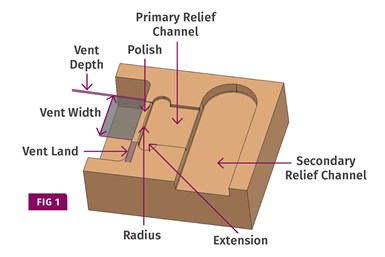
Vent nomenclature
In order to maximize your processing window, vents should be as deep as possible without causing flash. That depth is based on several factors, such as the type and grade of material, part geometry, mold construction and process parameters. Anything less than the maximum depth is inefficient and may require additional vents—assuming there is room to add them.
Most material manufacturers specify a recommended vent-depth range for their resins. For runny, non-viscous, crystalline resins such as nylon, PE, or PP, the recommended vent depth can range from 0.0005 in. to 0.0010 in. More viscous amorphous materials, such as PC, TPU or PEEK, can have a recommended vent depth range from 0.0010 in. to 0.0030 in. If you’re a mold designer with one of those vent-depth “rule-of-thumb” charts for different types of materials tacked to your wall, keep in mind that it is only a guideline. Depending on the material manufacturer, the MFI, filler content and additives, each individual material grade can have a distinctly different vent-depth recommendation.
The wall thickness of the part is an important factor to consider when selecting the vent depth. This phenomenon was described in the January 2018 Plastics Technology article titled Determining Vent Depths in Injection Molding, by Suhas Kulkarni of FimmTech Inc. Kulkarni, with the help of Distinctive Plastics, a custom molder in Vista, Calif., built a test mold with 18 tabs of various thicknesses and vent depths.
Vents should be as deep as possible without causing flash.
They were able to prove that as the wall thickness increased, the depth of the vent could also increase without flashing. Kulkarni explained, “There are two reasons for this. As plastic is forced into thinner sections, the flow rate of the plastic in the area increased. The increased flow rate increased the shear rate and led to a reduction in the viscosity, making the plastic flow easier, resulting in flash. The reduced viscosity also allowed a reduced pressure drop, increasing the end-of-fill pressure, resulting in flash.”
To put this into layman’s terms and applying it to other areas of an injection mold: Anywhere you have a condition where the material viscosity will decrease due to shear, such as near the gate, or at the bottom of a thin rib, you should use a vent depth on the low side of the recommended range. Conversely, anywhere that the material viscosity will increase due to lack of shear, such as along the runner, or in thicker sections of the part, you can use a vent depth on the high end of the recommended range. Additionally, I have learned over the years that anywhere a vent is perpendicular to the direction of material flow, that vent can also be slightly deeper without flashing.
Vent Land Length
The longer a vent’s land length, the more pressure it takes to exhaust the air through it. The more pressure it takes, the more compression there will be inside the cavity, and the higher the risk of the part burning and the steel eroding. The late Bernie Olmsted, a molding expert and author of several books, used this analogy: “Consider a small-diameter drinking straw. Cut off a piece 1/2 inch long. Blow through it. Now take the rest of the straw and blow through it. You will experience a decided difference in the required effort (pressure) between the two sections of the straw.”
In addition to the increased pressure, longer land lengths will clog with debris sooner than shorter ones. Shorter vent lands also tend to stay cleaner because the compressed air has an easier time blowing any debris out during injection, especially with fast fill rates. Vents are not self-cleaning—they’re self-clearing.
Flash will only occur if a vent is too deep – not if it’s too wide.
The knowledgeable consensus is that 0.030 in. is the minimum land length. Some say it should also be the maximum length. However, a lot of this depends on the size and geometry of the part. A large contoured mold, such as a car bumper, can have several factors that can adversely affect the ideal vent depth and land length—such as cavity volume, flow length, wall thickness, bearing surface, preloaded components, machining accuracy, even platen concavity. That is why I agree with fellow Plastics Technology contributor, Randy Kerkstra, who suggests starting off at 0.080 in. and then reducing it if an issue develops, such as burning or higher-than-expected injection pressures. One thing to keep in mind is that the technical design guides from most material manufacturers intentionally err on the side of caution. For example, one highly respected manufacturer of polycarbonate recommends a vent land length of 1/8 to ¼ in.—as if to imply it’s not very important.
Vent Width
Vents are often ¼ in. wide for small parts and ½ in. wide for larger parts, because these are standard widths of a surface-grinding wheel, and smaller cavities have less air to exhaust than cavities with large volumes of air. There is no law that says a vent can’t be smaller than ¼ in., which is often necessary on very small parts or in difficult-to-vent areas, but narrow vents will require more frequent cleaning. There is also no law that says vents can’t be as wide as the designer or processor feel is needed. Flash will only occur if a vent is too deep—not if it’s too wide. I prefer to go no less than ½ in. wide, because the end-of-fill location(s) can shift position a little due to variations in the process. In the majority, but not all, cases, you want a vent at the end-of-fill location(s).
The goal is to make each vent as efficient as possible.
Vent Surface Finish
If milling is the only possible way to add a vent due to the geometry of the part, never leave a milled finish on the surface. Even if the vent is surface ground with a 120 to 240 grit wheel, it should then be polished with a 600 to 800 grit stone for a finer finish. Perform both the grinding and stoning operations in the direction that the air flows. Many mold makers go the extra mile and polish the vent with diamond paste on a felt bob. I’ve heard several people mention that polished vents are “self-cleaning,” but I’ve never seen one. I can attest to the fact that a well-polished vent does extend the preventive-maintenance period, but give it a few thousand, or tens of thousands of cycles, and there’s no avoiding a sticky buildup of residue with most molding materials. Note: It should go without saying that you should not install, stone, or polish the vents until after the cavity is polished and the extra stock on the parting line has been removed.
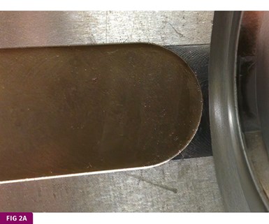
Poorly machined vent-relief channel with inefficient half-round shape.
Vent Relief
The machined area connected to the vent is called many things, such as the vent relief, vent dump, secondary vent, vent groove, or relief channel. This machined area feeds into a channel, which can feed into another channel, and sometimes into a third channel. I don’t believe anyone has given these channels a name—and they should. I identify these channels similar to how we already identify various sections of a cold runner: primary, secondary, tertiary, etc. The primary relief channel is the one connected to the vent. Several of these primary relief channels often feed into a secondary relief channel. On occasion, two or more of these secondary channels feed into a tertiary relief channel, until the air is finally exhausted into the atmosphere.
The width of the primary relief channel should be the same as the width of the vent. Anything narrower would be inefficient. Anything wider would be unnecessary. When it comes to how deep the primary relief channel should be, there are several rules of thumb. The most common notion is they should be 0.010 to 0.015 in. deep. If you consider that the depth of the channel should not impede the flow of air escaping from the mold, then 0.010 to 0.015 in. is usually sufficient. However, if you also consider that the relief channel collects the sticky residue from the outgassing material, this depth is on the shallow side. My own rule of thumb is the depth of the primary relief channel should be at least 10 times the depth of the vent, but with a minimum depth of 0.020 in. The minimum depth recommendation is because over the lifespan of many molds, the parting line is occasionally ground to repair damage caused by flaking sub-gates, nozzle strings, and other debris.
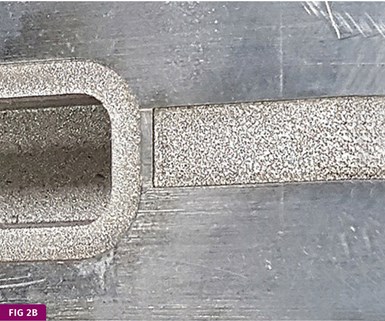
Better to use a small-diameter end mill or EDM to create corners. But if you EDM the relief channels, you must polish them afterwards.
When machining the primary relief channel, be aware that it should never look like the one in Fig. 2A. It irks me to see this exact shape in many mold-design guides and textbooks. When you use a large-diameter cutter, the very center of the vent has the correct land length, but that length increases dramatically as it moves toward the outer edges. The vent may appear to be ½ in. wide, but in reality, the effective width is only about 1/16 in. and it won’t take long for the center of this vent to wear out. At the very least, use a small-diameter end mill to create some semblance of corners. Better yet, mill a narrow channel perpendicular to, and slightly longer than, the width of the vent. You can also EDM the relief channels to get sharp corners, but they would need to be polished afterwards (FIG 2B). Whichever method you chose, the goal is to make each vent as efficient and uniform as possible. Look at it this way: It would take several vents similar to the one depicted in Fig. 2A, to be equivalent to just one properly machined vent.
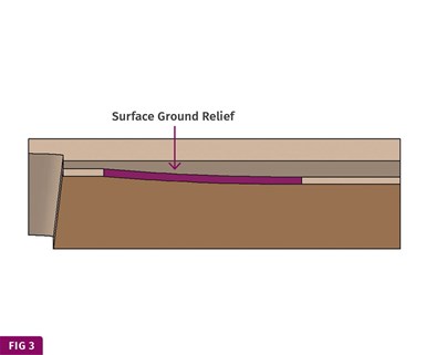
Extended land length due to surface grinding the primiary vent relief channel
If you surface grind the primary vent-relief channel, as shown in Fig. 3, you should mill out the arc created by the grinding wheel. Otherwise, the effective land length of the vent will be much longer than was originally intended. I do know one seasoned mold designer who prefers this method, so as to have a very short land length, but with sufficient steel left to support it.
There are also several rules of thumb as to how wide and how deep the secondary relief channel should be. Discard these “rules” and break out your calculator. If you have 10 vents that are ½ in.-wide × 0.020 in. deep going through primary relief channels, which feed into a secondary relief channel, you have 0.010 in.2 of cross-sectional flow area. The secondary relief channel must have at least an equal amount of cross-sectional flow area as all these vents combined. Let’s say the secondary relief channel is 3/8 in. wide. The minimum depth should therefore be 0.010 in.2 / 0.375 in. = 0.027 in. deep. However, I like to go 1.5 to 2 times this depth to guarantee there is no pressure drop caused by rough mill marks and 90° turns.
If you have two or more secondary relief channels feeding into a tertiary relief channel, the same rule applies. The cross-sectional area of the tertiary relief channel must be at least equal to the sum of the cross-sectional areas of the secondary relief channels feeding into it—plus a safety factor of 1.5 to 2.
If the mold does not have a lot of bearing surface, or is made of non-heat-treated steel, you might consider making the relief channels narrower, but deeper. This provides you with the necessary flow area, but leaves you with more parting-line surface area to help prevent hobbing. If you choose this option, it’s a good idea to add 5° or 10° of draft to the side walls (trapezoidal shaped). The plastic will be easier to remove in the event of flashing the mold.
I have seen more than my fair share of cracked cavities and cores. When allowable, I always recommend putting a small radius on the end of every cutter—even on vent channels. Sharp inside corners; stresses from heat treating, flaws and inclusions in the base metal; and fatigue stress from repeated high-pressure clamping can ruin your day.
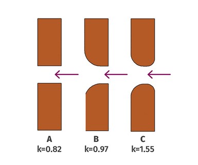
Fig. 4 Orifice coefficients of flow for various shapes.
Vent Shape
As described earlier, the length of the vent land has a direct effect on the pressure required to force air through it. The shape of the vent also has an impact on that pressure and on its efficiency. There is a numerical constant called the Orifice Coefficient of Flow or Coefficient of Discharge, used in calculating fluid flow efficiency through a constriction. Air is considered a fluid, and a vent is obviously a constriction. Various shapes of the leading and trailing edges of a constriction are assigned a dimensionless number, K. The larger the number, the lower the pressure drop—and vice-versa. Some examples of the various shapes are shown in Fig. 4. Based on this information, it would be a good idea to add a radius or at least break the edge of the back side of vents, similar to the shape shown in example “B.”
ABOUT THE AUTHOR Jim Fattori is a third-generation injection molder with more than 40 years of molding experience. He is the founder of Injection Mold Consulting LLC. Contact jim@injectionmoldconsulting.com
Related Content
Understanding Melting in Single-Screw Extruders
You can better visualize the melting process by “flipping” the observation point so the barrel appears to be turning clockwise around a stationary screw.
Read MoreThe Fundamentals of Polyethylene – Part 2: Density and Molecular Weight
PE properties can be adjusted either by changing the molecular weight or by altering the density. While this increases the possible combinations of properties, it also requires that the specification for the material be precise.
Read MoreHow to Select the Right Cooling Stack for Sheet
First, remember there is no universal cooling-roll stack. And be sure to take into account the specific heat of the polymer you are processing.
Read MoreWhere and How to Vent Injection Molds: Part 3
Questioning several “rules of thumb” about venting injection molds.
Read MoreRead Next
Back to Basics on Mold Venting (Part 1)
Here’s what you need to know to improve the quality of your parts and to protect your molds.
Read MoreFor PLASTICS' CEO Seaholm, NPE to Shine Light on Sustainability Successes
With advocacy, communication and sustainability as three main pillars, Seaholm leads a trade association to NPE that ‘is more active today than we have ever been.’
Read MorePeople 4.0 – How to Get Buy-In from Your Staff for Industry 4.0 Systems
Implementing a production monitoring system as the foundation of a ‘smart factory’ is about integrating people with new technology as much as it is about integrating machines and computers. Here are tips from a company that has gone through the process.
Read More

