Breaking Down Hot Runner Maintenance
Improving a manifold’s maintenance plan requires specific skills and knowledge of its functioning areas.
Working on hot runner manifolds requires certain skills and training because of the heat expansion of the steel plates and components. If the mold and repair technician does not understand and cannot account for these effects, he or she may have trouble with mechanics, safety and effective processing. Developing a better maintenance plan for manifold service or repair requires a general knowledge of hot runner systems. That knowledge includes things like the system’s components (fixed or valve gates, heaters, thermocouples, wiring paths), maintenance history, complexity level and required maintenance skills. More importantly, proper manifold maintenance depends upon an understanding of its critical functioning areas (flow paths, seal areas, cooling channels) and its dimensional relationship with the cavities (gates and nozzle tips).
The first step when working on any manifold is identifying the goal of the work, which determines and verifies the specific maintenance plan. For example, is it routine preventive maintenance, or a new or repetitive problem with a mold or part? When it comes to manifolds, the more specific question may be, is preventive maintenance done at an appropriate cycle count? Or, does the PM cycle frequency need adjustment?
Once the shop sets a goal and strategizes a maintenance plan, there are general preparation, disassembly and re-assembly steps to follow for proper hot runner maintenance. These steps are general guidelines when working on most systems. Always check with your hot runner supplier for their recommendations on the proper techniques and sequences.
Preparation Guidelines
- Go to the crib and verify that the necessary tooling is in-house to support the maintenance plan. Necessary tooling includes heaters, thermocouples, nozzles, nozzle tips, valve pins and valve pin bushings.
- Confirm the estimated downtime with the production/molding department.
- Review past maintenance history to determine the most efficient method for mold and manifold disassembly. Most manifolds are removed from the manifold retaining plate in the horizontal position for safety and efficiency, but some are removed more easily in the standing or the vertical position.
- Determine a proper removal procedure for the electrical control box (for example, with nozzle heater and thermocouple wires connected or individually disconnected) and the best disconnection method for the manifold heater wires (for example, disconnected from the manifold or from the control box).
- Identify critical areas and special tools that may be necessary for disassembly. Examples include wooden spacer blocks to carry the manifold weight and to avoid damage to protruding nozzles, rubber caps to protect nozzle tips during manifold removal, eyebolts versus jack screws, a hand lift versus an overhead hoist and a technician’s hands versus a slap hammer for valve pin removal.
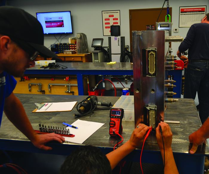
- Check all heaters and thermocouples for resistance and shorts using an ohmmeter before disassembly, then record the readings. To do this faster, use a portable hot runner mold testing system, such as the Mold Checker from Fast Heat, which tests hot runner manifolds to ensure that resistances of all thermocouples and heaters are within range.
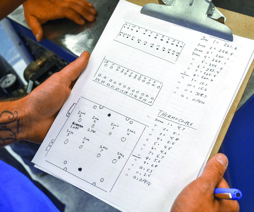
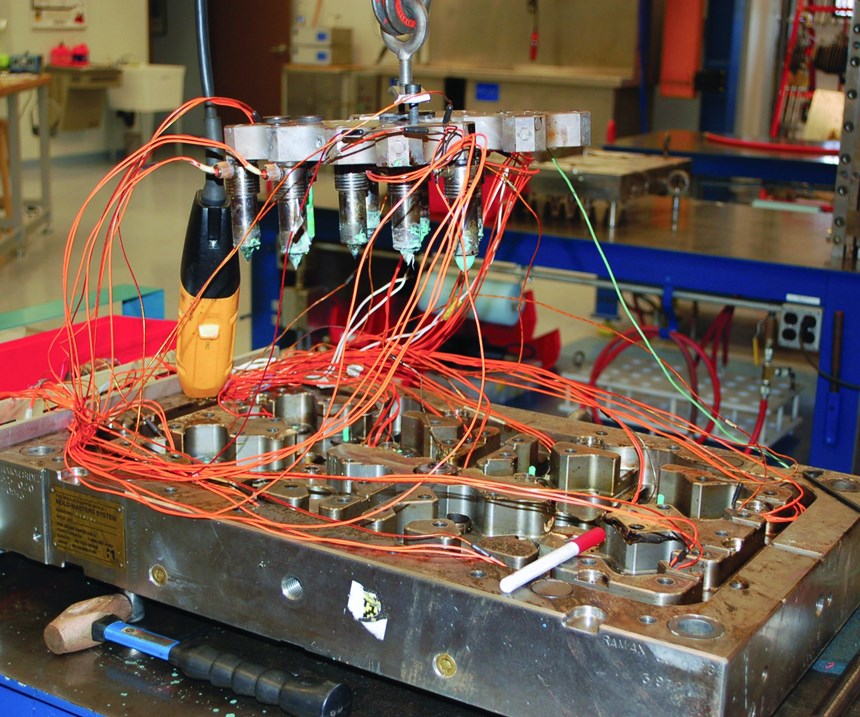
- Map the position of each thermocouple and heater to verify their connection to the correct pin on the electrical connectors. Record the results (see Figure 1).
Disassembly Guidelines
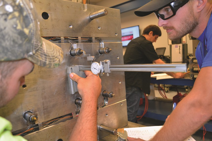
- Remove the “A” cavity plate in a fixed gate system (no valve pins) to expose the nozzle tips before removing the rear clamp plate. Then measure and record the distance from the nozzle tip to the nozzle plate (see Figure 2). This dimension is critical to the relationship between the gate area and the land area and can be the root cause of parts that suffer long gate issues (like a spike of plastic sticking out from the gate location). This dimension also serves as a reference point to ensure that the nozzles are positioned correctly after the mold is reassembled.
- Ground the electrical controller directly to the mold, if using a controller to check the heater and thermocouples and if using wooden spacer blocks. The blocks will prevent the mold from being grounded through the steel bench, creating a shocking situation.
- Warm up nozzles to 250°–350°F (depending on the resin) when removing the pins from a valve-gate system. This eases the extraction of the valve pins from the manifold system which prevents the resistance of cold plastic that can damage the valve pins.
- Move the valve pins back or to the open position while they are warm. This prevents damage to the tips on delicate valve pins and protects them if the cavity plate gets jammed on the leader pins and does not come off evenly during its removal.
- Number every tip to a home position for accurate reassembly, so the valve pins take a seat (or running fit) in their related valve pin bushing during production.
- Handle valve pins carefully when removing them, placing them on a bench or in a cleaning basket when cleaning and drying them and when returning to the bench and reinstalling them into the mold. Careless handling will create dings or bend the fragile tips.
- Take additional reference measurements from the manifold plate to the manifold or to any expansion spacers located at the top of the manifold before removing any bolts that are securing the manifold. These measurements help verify that everything was put back together correctly. Measure closest to the corners of the manifold to determine the flatness of the manifold in relation to the manifold plate. If one or more corners varies by 0.010 inch or more, it is likely that the manifold does not sit flat on the nozzles, which points to a potential tooling stack problem.
- Clean and stone an area before taking any measurements. This helps ensure more accurate readings.
- Measure from the top of the bridge to the manifold plate and down to the manifold when a manifold bridge is part of the system. This measurement is useful during reassembly.
- Note wiring routes through the plates and use wire labels to identify the correct heater and thermocouple positions.
- Remove the manifold bolts and carefully lift out the manifold once all the measurements are taken and all the wire clips are removed. If the nozzles are bolted to the manifold plate, removing the manifold might require extra force to break the plastic connection between the nozzles and the manifold feed channels.
- Document this procedure with images, as damage can occur if prybars are jammed in the wrong area. If the nozzles are not bolted to the nozzle plate, they may remain attached to the manifold (see Figure 3). At this stage, use extreme caution to ensure the nozzles are not bumped or broken, damaging the tips. Some technicians prefer to pull the manifold while it is hot, which helps to break the nozzle/manifold connection. Wear proper gloves and other appropriate gear when using this method.
- Clean all tooling carefully. Do not haphazardly pile valve pins and other delicate components into a single steel cleaning basket.
- Make sure there is no plastic or residue at the sealing points located at the junction of the plastic flow paths.
Re-assembly Guidelines
- Be careful using soft brass, aluminum or copper tools during reassembly, as they easily flake or chip. These chips can fall into areas that cause sealing problems and slow leaks.
- Use the right tool for the right job to avoid excessive force for reinstalling the tooling. Stop and identify the cause of any resistance before breaking out the big hammer.
- Work methodically during reassembly. Do not forget to install bolts, dowels and spacers, as this will require the manifold to be disassembled again. Remember that manifolds fail because of the way we put them together, not because of the way we take them apart.
- Read the feedback from your hands and tools. For example, some root causes of manifold leaks include nozzles that fit tightly into bores, manifolds that rock (or do not sit flatly) after being reset onto nozzles and dowel pins that are not properly lined up or engaged.
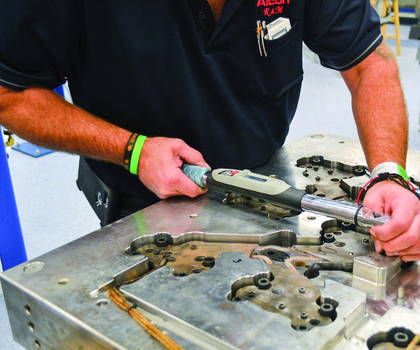
- Torque the manifold bolts to manufacturer specifications. If those are not available, then use standard torque settings for the bolt sizes in question. Use a balanced, corner-to-corner pattern if a manufacturing torque pattern is not available (see Figure 4).
- Use an anti-seize product on the bolt threads and under the head to prevent waste in torque force. Technicians often waste as much as 30 percent of torque force to overcome friction.
- Re-heat nozzles to ease installation if installing valve pins.
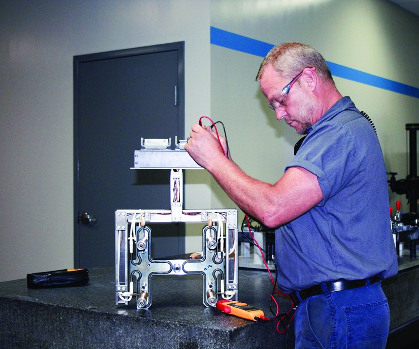
- Test manifolds, nozzle heaters and thermocouples with an ohmmeter or a portable hot runner mold testing system before bolting it onto the back-clamp plate.
- Recheck heaters and thermocouples for shorts and connectivity issues after the clamp plate is reinstalled and tightened, and then document the readings.
- Make sure there is no variation in temperature between the cavity plate and the nozzle plate when installing a cavity plate to a nozzle plate or working on manifolds in the press while changing or cleaning nozzle tips. For example, a 25-degree difference in temperature could cause the center-line distance of the nozzles to be off by 0.004 inch over 24 inches in relation to the cavities, resulting in misalignment between the cavities and nozzle seals. This will damage the seals and cause slow, catastrophic plastic leaks.
- Document all issues throughout maintenance, such as poor wiring conditions, wire pinch points, worn electrical connectors, stripped threads and damaged electrical boxes. Take pictures along the way for future reference.
- Create and use maintenance manuals to advance the team’s knowledge base about the most appropriate, efficient and safest methods to use when working on a specific manifold system.
Although working on hot manifolds is an area of mold maintenance that requires a
bit more knowledge, focus, patience and hand skills, these general preparation, disassembly and re-assembly guidelines will help structure and simplify a hot runner maintenance plan. The key is being proactive, creating a data-driven shop environment and encouraging continuous improvement across the toolroom.
About the Contributor
Steve Johnson
Steve Johnson is the president of MoldTrax, which provides specialized course work, hands-on bench training, maintenance software, maintenance products, toolroom design and maintenance efficiency auditing.
Related Content
How To Design Three-Plate Molds – Part 4
There are many things to consider, and paying attention to the details can help avoid machine downtime and higher maintenance costs — and keep the customer happy.
Read MoreHow to Design Three-Plate Molds: Part 5
There are many things to consider, and paying attention to the details can help avoid machine downtime and higher maintenance costs. In this installment, the focus is on design and placement of sucker/puller pins.
Read MoreWhy Shoulder Bolts Are Too Important to Ignore (Part 2)
Follow these tips and tricks for a better design.
Read MoreWhere and How to Vent Injection Molds: Part 3
Questioning several “rules of thumb” about venting injection molds.
Read MoreRead Next
Making the Circular Economy a Reality
Driven by brand owner demands and new worldwide legislation, the entire supply chain is working toward the shift to circularity, with some evidence the circular economy has already begun.
Read MorePeople 4.0 – How to Get Buy-In from Your Staff for Industry 4.0 Systems
Implementing a production monitoring system as the foundation of a ‘smart factory’ is about integrating people with new technology as much as it is about integrating machines and computers. Here are tips from a company that has gone through the process.
Read More
