CT Scanning Gives Precision Molder X-Ray Vision of Part Quality
It beats other techniques for measuring critical part dimensions, and it provides unique visibility inside parts, nondestructively. One molder’s experience illustrates the benefits.
If you were (or still are) a fan of DC Comics’ Superman, you no doubt envied his “x-ray vision” that allowed him to see through walls and other solid masses. Today, a growing number of plastics molders are finding that “super power” is available to them for real and is a valuable time and cost saver in ensuring quality of tight-tolerance parts.
One such molder is Prism Plastics, a producer of precision plastic components, primarily functional safety-critical parts for the automotive industry. Examples include components of seatbelts and brake and fuel systems. Founded in 1999 with a single press, Prism has grown to a $30 million business with 31 presses at three plants in Chesterfield Township (the headquarters) and Port Huron, Mich., and Harlingen, Texas. Together, they produce 500 million parts a year with <1 ppm reject rate, according to Jeff Ignatowski, director of sales and marketing. Only three people run production at each facility per shift, so preventing quality problems is a high priority, to say the least.
NEW MEASURING TOOL
Since last year, Prism has embraced industrial computed tomography (CT) scanning as a superior method of validating new parts and solving quality problems. It now uses CT scanning regularly on new projects. “We got involved with this technology largely in response to some of our Tier 1 customers, who were heading in the same direction,” says Matt Trisch, Prism’s engineering manager “Our engineering team generally uses CT scanning on the front end of projects to help quickly identify trouble spots and address challenges before parts go into production.”
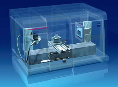
Industrial CT scanning is similar to the medical procedure, and dental technology, except for the energy level of the x-rays used and the level of detail that can be resolved. The most common type of industrial CT used in the plastics industry is a cone-beam CT.
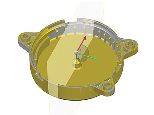
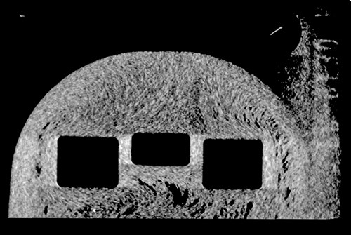
A part is placed on a table in the scanner and rotated 360° while exposed to an x-ray beam. A standard scan takes from 10 minutes to two hours. The beams are captured in a digital detector, and multiple 2D images through the part (in the form of picture files, such as are used in image processing) are combined in software to render a 3D image. In that rendering, higher density or thicker objects appear lighter, and lower density or thinner objects show up darker. For most plastic parts, a calibrated CT system can provide accuracy to 7-10 microns on average, with resolution depending on part size. Trisch says 30-micron resolution is typical for Prism’s parts. for CT systems designed specifically to scan micro parts, accuracy can increase to sub-micron levels.
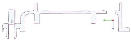
Because of the high cost of CT scanners, which can range from a few hundred thousand dollars to $1 million or more, very few plastics molders invest in their own scanning equipment (giant Nypro is an exception). Prism uses outside service bureaus in Michigan and nearby Windsor, Ont. Because the data files generated by the scans are quite large, Prism invested $25,000-30,000 in Geomagic software from 3D Systems to manipulate the scan data—rotate and slice 3D images with color-coded profiles of density or thickness, display 2D sections, and overlay scans and CAD geometry.
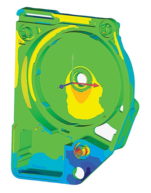
At Prism, the STL output from the CT scan can be aligned to the native CAD file by a “best fit” method or to the print datums. Once aligned, a color map can be generated to show where the part falls within print tolerance. A color gradation scale can be used to show the to-print areas in green and any not-to-print areas in red or blue. Unlike traditional methods such as CMM, the problem areas are made known immediately. With a traditional CMM layout, the problem areas are revealed gradually as each print dimension is checked in series.
“While many injection molders don’t yet utilize CT scans, they are a perfect fit for the tight-tolerance, difficult-to-mold pieces that are the heart of our business,” comments Ignatowski. “This technology allows us to push the envelope for cavitation, runner design, and other features that may make for a more difficult processes to engineer, but also increase output and efficiency while cutting waste.”
FASTER, BETTER, CHEAPER
Trisch calls CT scanning “the next greatest thing.” He Says, “We’re working toward using it on all new projects.” He cites several advantages over other metrology techniques. One is that it is not a line-of-sight method like optical scanning. That provides visibility of internal features, and even within the solid wall, of a part. Another is that CT scanning is nondestructive. It allows inspection and measurement of internal features without having to cut the part into sections or pour liquid polymer into the part to make a cast, both of which can change the very dimensions the molder seeks to measure. And unlike white-light or laser optical scanners, it does not require spraying the part with a neutral gray, non-reflective coating, which slightly changes dimensions and can obscure other subtle features of a part. Further, CT scanning is non-contact, unlike touch CMMs (coordinate measuring machines) and does not require fixturing of very delicate parts (except in cases where highly flexible materials like silicone rubber might droop).
Trisch says a key reason for moving to CT scanning is better measurement repeatability and reproducibility (gauge R&R) than with CMMs. “Our tolerances are often ± 0.1 mm or less, and some parts allow only 30 microns total variance. We ship a lot of parts to Mexico for assembly. Due to the influence of operator technique in CMM setup and operation, measurements of the same part at our plant and at the customer’s facility can differ by more than the print tolerance allows.” Repeatability of CT scanning is described as “nearly perfect,” within 97-99.5%. Speed and cost also favor CT scanning for the kind of safety-critical parts molded by Prism Plastics. CT scans generate millions to trillions of data points, even on non-geometric surfaces, relatively quickly. “We can get same-day turnaround from our service bureaus if we need it,” says Trisch, though a week is more typical for a full 3D layout of scan data. A traditional CMM layout can take much longer for a complex part. By providing a color map of a “part-to- CAD” comparison as the PPAP (production part approval process) layout, lead time to production readiness can also be reduced. The lead time for traditional inspection and generation of a layout report is eliminated.
Cost of a scan depends on part size and complexity. For a seatbelt retractor cover—a relatively large part for Prism—a scan with dimensional analysis could cost in the vicinity of $2000, which is about half of what comparable CMM measurements would cost.
Just as color maps can be generated for a “part-to-CAD” comparison, CT scanning is convenient for “part-to-part” comparisons. This helps Prism quickly determine if a part is “the same” as it was at initial PPAP. This speeds up revalidations as well as corrective actions and root-cause analysis of problems.
The resolution of CT scans is so fine, Trisch says, that “we can see ejector-pin marks on the part or transfer to the part surface of cutter marks on the tool cavity.”
Trisch also admires the capability to “see through the part” with CT scanning. “We mold parts like connectors for brake and fuel lines that have internal undercuts where the bore I.D. forms a seal with an O-ring. Traditionally, we would have to pour in liquid rubber and then crack the part open. It can be hard to get the rubber cast out without damage or distortion.”
He notes that CT scanning can make parts transparent to more than just internal geometry. “We can see glass distribution or orientation in the part wall. Because glass has a different density from plastic, we can ‘turn off’ the plastic—make it disappear, in effect. In one case, this helped us understand the source of a warpage problem.”
Voids, weld lines, and tiny nonfills or flash also become apparent with CT scanning. “We have learned a lot about our processes from these scans,” notes Trisch. “We were molding connectors that were supposed to have a 90° bend, but the angle came out wrong. We were able to solve the problem—eliminate voids and thick areas— by changing runner and gate sizes. It’s always better to change steel than to stand on our ear to tweak the process.”
VIEW FROM A SERVICE BUREAU
Jesse Garant & Associates (JG&A) Metrology Center is one of Prism’s providers of CT scanning services. Jesse Garant, who has a background in tooling and injection molding, said he decided after reading a September 2008 article on industrial CT scanning in Plastics Technology that this was an up-and-coming field and he founded a service company devoted to the technology.
Garant now has his main scanning lab in Windsor, Ont., and a second small office in Detroit. Besides plastics, his services are used to scan glass, metals, and multi-material parts. He also offers free viewing software to examine the files.
Garant says CT scanning can be used to validate injection molds—for example, overlaying part scans to compare one cavity to another in a 32-cavity stack mold. The same approach can be used to compare one mold to another in a multi-tool program. He adds that inspecting small steel tooling inserts with undercuts, such as for gears and splines, can be difficult to accomplish by methods other than CT scanning.
He says CT scanning has a natural fit in inspecting parts or tooling for micromolding and tiny optical parts. For larger parts, such as plastic bumpers, he says, other techniques such as white-light or laser scanning “may give you better results for a lot less money.”
His average customer uses CT scanning for part qualification or failure analysis, either in preproduction or during production. “More proactive companies use CT scanning for new product development, because it allows them to validate faster and better.” By better, he means that it can identify voids and pores in stress areas of a part, which may be invisible to other inspection techniques.
This capability is especially valuable in the fast-growing area of multicomponent injection molding. By seeing through the part, CT scanning can examine the interface between a substrate and the overmolded resin (even thermoplastics and LSR) to detect voids or porosity that would compromise bond strength.
Related Content
Three Key Decisions for an Optimal Ejection System
When determining the best ejection option for a tool, molders must consider the ejector’s surface area, location and style.
Read MoreWhat You Need to Know About Leader Pins and Bushings
There’s a lot more to these humble but essential mold components than you might suspect. Following the author’s tips could save much time, money and frustration.
Read MoreHow to Design Three-Plate Molds, Part 1
There are many things to consider, and paying attention to the details can help avoid machine downtime and higher maintenance costs, and keep the customer happy.
Read MoreDesign Your Tools for Moldability ... and Maintenance
In the initial design phase, when considering the structure and elements of the tool, are you designing them to be maintenance friendly? Canon Virginia has used this approach and preventive maintenance to make tool replacement a thing of the past. You can, too. Here’s how.
Read MoreRead Next
Industrial CT Scanning Speeds Mold Qualification
Qualifying a mold often can take weeks and involve several costly and time-consuming steps.
Read MoreSee Recyclers Close the Loop on Trade Show Production Scrap at NPE2024
A collaboration between show organizer PLASTICS, recycler CPR and size reduction experts WEIMA and Conair recovered and recycled all production scrap at NPE2024.
Read MoreFor PLASTICS' CEO Seaholm, NPE to Shine Light on Sustainability Successes
With advocacy, communication and sustainability as three main pillars, Seaholm leads a trade association to NPE that ‘is more active today than we have ever been.’
Read More

