‘Expansion Molding’: New Method For LSR Micro-Molding
X-melt or expansion molding technology was originally developed by Engel to fill thin-wall parts that require extremely fast injection.
X-melt or expansion molding technology was originally developed by Engel to fill thin-wall parts that require extremely fast injection. X-melt technology enables the molder to achieve much higher injection rates than are mechanically possible by the injection machine. (If that sounds impossible, read on.) Recently Engel has expanded the scope of X-melt to include low pressure micro-molding using liquid silicone rubber (LSR).
HOW & WHY IT WORKS
X-melt is expansion molding. It relies on the inherent compressibility of plastic melts and uncured LSR. In essence, the procedure is to first accumulate the shot volume in front of the screw and then move the injection screw to its final forward injection position while the material is held in place by cold-runner (hot-runner for thermoplastics) valve-gate nozzles. The LSR is compressed using this pre-injection stage to create a spring or stored energy. The amount of energy is determined by the X-melt pressure—the set pre-injection pressure—and the size of the cushion or spring in the injection unit.
Unlike other liquids that are not compressible, LSR is 5% to 7% compressible, depending upon the material durometer and supplier. In the X-melt process, the LSR is held in this compressed state for a set time to allow the LSR material pressures in the injection unit and cold runner to stabilize. After this set X-melt time has expired, the valve gates are opened and the material “srping” is released to expand spontaneously into the cavities. As the molded parts fill, the pressure reaches an equilibrium point at which filling stops, and the valve gates are closed.
The green line on the graph in Fig. 1 indicates the injection pressure. The graph shows the X-melt pressure of 2800 psi and an X-melt holdup time of 1.6 sec. It also shows the rapid pressure drop as the material is released into the cavity. The bottom of the curve is the point of equilibrium or residual pressure. Since a traditional hold pressure or time is not used with X-melt technology, this becomes the hold sequence. The white vertical line on the graph indicates the point in the cycle where the valve gates are closed. The point of equilibrium can be increased or decreased by raising or lowering the X-melt pressure setpoint and also by increasing or decreasing the cushion length.
This effectively raises or lowers the hold pressure of the process. The valve-gate timing can be increased or decreased to adjust the hold time of the process. The result is a process that is no longer dependant upon screw position for accuracy. The premise of X-melt technology is fixed pressure + fixed orifice = repeatable flow rates.
WHY IS THIS IMPORTANT?
Consider a micro-molding application using a 12-mm diam. injection screw and a shot size of 0.010 g. This would result in a total injection stroke of 0.0031 in., which might be difficult enough to repeat, but then also consider the dependency of an exact metering stroke and exact material pressure during metering. Consider that a change in screw position of only 0.0005 in. would amount to over 15% variation in total shot size. Since X-melt is dependent upon achieving a set pressure and opening the valve gates or injection nozzle for a set time, screw position is no longer important.
This also eliminates variations due to fluctuating metering pressures. In many micro-molding applications, opening and closing the metering valve mounted on the feed throat introduces more material than the total shot size.
Exact metering has always been a challenge in LSR micromolding, often requiring specialized equipment. Since the standard process is position dependent, metering must be included in each cycle to ensure a consistent starting point for injection. X-melt technology is not dependent upon screw position, so we can mold several shots before requiring a metering cycle. This means longer metering cycles and more screw rotations, resulting in a more homogeneous mixture and better color dispersion.
X-MELT IN ACTION
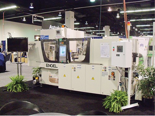
In a recent case study, Engel compared X-melt technology with a standard injection process using LSR in a four-cavity injection mold. The machine used for the study was an Engel evictory 80/30 US hybrid tiebarless machine (Fig. 2). The machine featured a servo-electric injection unit and a servo-controlled hydraulic system for clamping and ejector functions. The plasticizing assembly was a standard LSR injection screw (18 mm diam.) and water-cooled barrel. The only machine requirements for X-melt are electric servo-driven injection (to be able to lock the screw in the pre-compression position, with no forward movement after the valve gates open) and an X-melt expansion-molding software package.
The mold selected was a four-cavity, valve-gated, cold-runner mold supplied by Roembke Manufacturing and Design, Ossian, Ind. The part was a medical umbrella valve with a weight of 0.1280 g. The total shot weight was 0.5119 g.
Although X-melt is capable of much smaller shot sizes, the first goal of the study was to compare the X-melt technology with a stable conventional injection process. The second objective was to show significant improvement using X-melt.
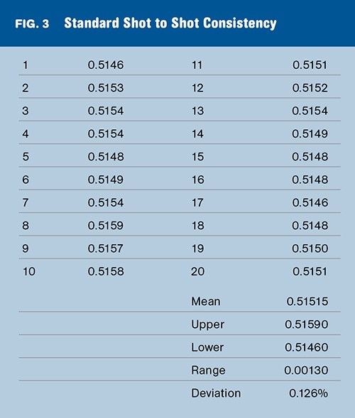
The study was conducted by running 100 shots and selecting 20 random shots for a weight study. For conventional injection, the total range of 0.0013 g and 0.126% deviation from mean indicate a very stable and repeatable process (see Fig. 3).
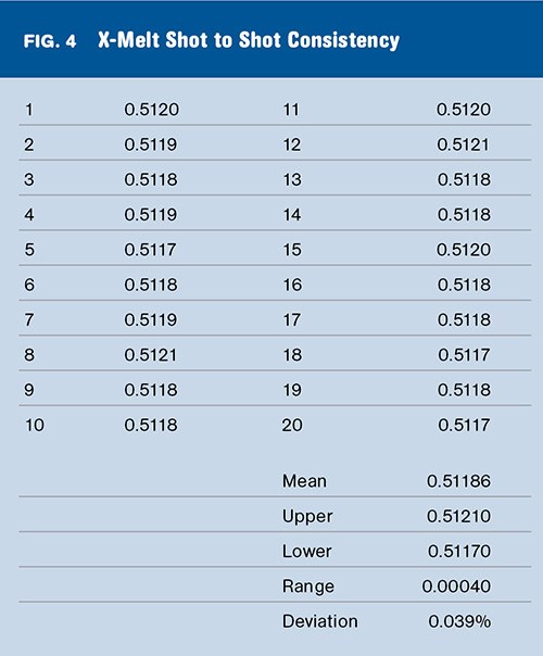
The second part of the study was to repeat the 100 shots with the X-melt function turned on. As you can see from the results in Fig. 4, there was a significant improvement in shot-to-shot consistency. The overall range was reduced from 0.0013 g to 0.0004 g and deviation from the mean of went down from 0.126% to 0.039%.
To better explain these results, we need to understand the results from each part of the trial. The standard-process part weights had a range of 0.004 g. These results actually show the repeatability of the screw position. The range of 0.004 g means the screw position varied 0.0006 in. from the mean. This is the effective repeatability of the injection machine used for the study.
The size of the shot will not have an impact on this repeatability, but as the shot size decreases, the range will become a higher percentage of the total shot size. For example, if the shot size were reduced to 0.250 g, the range of 0.0004 g would mean deviation from the mean of 0.8%. Since the X-melt technology does not rely on screw-position repeatability, the percentage of deviation from the mean remains the same regardless of the total shot volume.
X-MELT CAPABILITIES & LIMITATIONS
To fully understand X-melt technology we must understand its capabilities and limitations. The above study shows the capabilities of X-melt for molding LSR shot sizes up to 0.5 g. The process has been tested with shot sizes as small as 0.015 g with very similar results in the percentage of deviation from the mean.
The limitations should be discussed in both theoretical and practical terms. Theoretical limitations are the maximum shot volume a specific injection unit is capable of when using X-melt technology. The 18-mm screw used on the test machine has a maximum injection capacity of 28.68 g. At 4000 psi, the material reached a maximum compression of 6%. This means a maximum filling capacity of 1.721 g.
At this point, the equilibrium pressure would be at 0 psi, but to maintain sufficient residual pressure, only 85% of the maximum filling capacity can be used.
Thus, the theoretical shot-size limit with the X-melt technology on the test machine would be 1.463 g. The practical limit can be described as the point at which the X-melt technology no longer shows a significant advantage.
As discussed earlier, when using a standard position-controlled injection process, the shot size has no impact on repeatability of the screw position. This means that as the shot size decreases the same range in screw position results in an increase in the percentage of deviation from the mean.
The inverse is also true: As the shot size increases, the same range in screw position will result in a smaller percentage of deviation from the mean.
The shot size used for the case study was 0.5119 g and the standard process resulted in a 0.126% deviation from the mean. If the shot size was increased to 1.03 g with the same range, the result would be 0.063% deviation from the mean. This would no longer be considered a significant improvement over the X-melt technology. The practical limit of X-melt technology for the test machine would be shot sizes over 1.1 g.
ADVANTAGES OF X-MELT
In addition to increased shot-to-shot consistency, as demonstrated by the case study above, the advantage of the X-melt technology is that it is a software addition to a standard LSR injection molding machine. This means that it can be turned on or off as needed. We indicated the practical limitation of X-melt on the test machine would be shot sizes up to 1.10 g, but with the X-melt software turned off, the machine could run a standard injection process with the maximum shot capacity of 28 g.
This would not be the case for machines designed specifically for micro-molding. Typically machines developed for micro-molding are designed with very small injection screws or plunger injection systems. These machines have very defined injection volume limits that cannot easily be changed without physically altering the machine.
The advantage of X-melt technology to the molder is a production machine that can also be capable of micro-molding or single-cavity prototype molding instead of a very costly specialized machine that has limited uses.
Metering performance is also improved when using X-melt technology versus a standard injection process in micro-molding. A standard injection process with a shot size of less than 0.2 g may use an injection stroke of only 0.003 to 0.006 in., depending on the screw diameter. This means virtually no screw rotation during metering. The signal for metering may last less than 1 sec, which causes no mixing of material in the screw and very little material movement through the static mixer. If a third stream for color is added to the LSR process, the color dispersion would be very poor.
With X-melt technology, several cycles can be achieved before metering is required. This allows for a more stable metering sequence, resulting in better mixing of material and better dispersion of third-stream components.
As X-melt is new for LSR, Engel has four customers currently using the technology for development and production. X-melt for thermoplastics is a more mature technology, with more than 30 machines in the field equipped with X-melt software.
About the Author
Steve Broadbent is LSR /elastomer project engineer at Engel Machinery in York, Pa. He joined Engel five years ago after 18 years at three rubber custom molders in jobs ranging from press operator to project engineer. Contact: (717) 764-6818; steve.broadbent@engelglobal.com.
Related Content
Ether-Based TPUs for Broad Range of Industry Applications
BASF’s Elastollan 1400 TPU series can be used for applications ranging from railway pads, hoses and profiles to show soles.
Read MoreMedical Grade TPEs for Biopharmaceutical Tubing
Teknor Apex expands its Medalist TPE portfolio.
Read MoreICIS Launches: Ask ICIS Generative AI Commodities Assistant
Said to be the first of its kind, this AI assistant will enhance access to ICIS’ intelligence and insights for the energy and chemical markets.
Read MoreGEON Performance Solutions Buys PolymaxTPE
Combined company aims to be global leader in thermoplastic elastomers.
Read MoreRead Next
Making the Circular Economy a Reality
Driven by brand owner demands and new worldwide legislation, the entire supply chain is working toward the shift to circularity, with some evidence the circular economy has already begun.
Read MoreSee Recyclers Close the Loop on Trade Show Production Scrap at NPE2024
A collaboration between show organizer PLASTICS, recycler CPR and size reduction experts WEIMA and Conair recovered and recycled all production scrap at NPE2024.
Read MoreFor PLASTICS' CEO Seaholm, NPE to Shine Light on Sustainability Successes
With advocacy, communication and sustainability as three main pillars, Seaholm leads a trade association to NPE that ‘is more active today than we have ever been.’
Read More


