Five Steps Toward a Flawless Flat Film Start-Up
A poor line start-up benefits no one … except your competitors. Follow these five steps to get your film line fired up seamlessly.
Many new cast film lines are built and commissioned every year and most of them start producing commercial product in short order, if not immediately. That said, there are occasions during a start-up where nothing seems to go well, to the point of disrupting the production schedule. At that point, questions are usually raised, sometimes loudly:
Why is this happening?
Whose fault is it?
What do we do to correct the problem?
Who pays for the changes?
As you can imagine, this is not a happy time to be involved in the process, but with a little extra attention, a lot of problems could have been avoided in the first place. The purpose of this article is to help you do just that.
Is there one main reason some lines start poorly? Usually, it’s related to the lack of a clear description of what the line is supposed to do, or a poor specification. What does that mean? First, you will generally get what you ask for, and if you ask for a film line, you will get a film line. But, if what you really wanted, for example, was a line to produce a barrier coextrusion for deep-draw thermoforming, you may instead end up with a line for cast PE or cast PP for bread bags. It’s all in how you ask (see sidebar below).
Assuming you have specified the line as exactly as possible, how can you make sure it starts to produce sellable goods in the narrowest time frame possible? There are five start-up steps every business owner, plant manager, project manager, and process engineer should know when installing and starting a new line. Perform these five steps in sequence during the start-up process:
1. Perform the “smoke test.” That is, turn the extruder on and make sure it stays on.
2. Ensure that all critical process safety or shutdown switches and indicators are operational. Any item that can cause a runaway must be checked carefully.
3. Check all of the moving parts of the line to be sure they turn in the right direction and don’t shake themselves to pieces or experience excessive wear at start-up.
4. Confirm the design calculations of each critical process component by measuring the actual performance with the materials you plan to use.
5. Start the line and begin the process of making the product to specification. Once again measure the performance against targets.
These five steps can be done in sequence as each component is installed, prior to shipping to your location, and in combination with other installed components. Step 4 is perhaps the most critical, as it determines whether the line will be able to produce product at the rate and quality you need for maximum productivity and profit.
Five steps—it almost sounds too simple, but performing these is necessary to ensure that all will be well when production is scheduled and new capacity is needed. A poor line start-up benefits no one, except perhaps your competitors.
Who is responsible for all of these checks? Ultimately that’s you, as the processor and purchaser; but who actually performs them, pays for necessary modifications, etc., is generally a combination of processor and suppliers.
At times there may be numerous suppliers responsible for the final outcome—for example, if you purchased upstream auxiliary equipment from one machine builder, the extruder from a second, the die from a third firm, and downstream systems from a fourth. In this case, your contract has to be clear in detailing which company is responsible for what. If your contract isn’t clear who is responsible for a poor startup, then you can only hope for honest suppliers who stand behind their equipment, or the courts as a last resort.
So let’s look at the purpose of each of the five steps and how it should be executed. The purpose of the “smoke test” is to find wiring or installation errors and to identify components that are “weak,” of poor quality, broken, or seemingly destined to fail early. This is particularly important for electronic systems, where components either fail early or after a very long period. Nothing is more frustrating or costly than waiting two weeks for a replacement board that had a resistor burn up while the full production staff is in place and ready.
Next, after everything is assembled, check all the emergency shutdown systems and emergency stop circuits before putting the line into operation. This means all of them, and it requires a disciplined and deliberate approach. These systems are there to protect the operators and the equipment from harm, so this step needs to be performed thoroughly.
Try to start the line with each safety circuit activated (it should not start), and power down the line by activating each one. Nothing is more terrifying than punching an e-stop and having nothing happen, or more frustrating than to have one activate when it—not you—wants to.
Now you are ready to “start the engines.” Lubricate everything and check oil levels etc. Check that everything that should turn does so in the right direction (and that they don’t turn if they should not), that the lubrication is working, that the equipment doesn’t make noises, shake, or run at high power. Take initial vibration signatures if you plan to a monitor vibration, and/or initial torque and power readings without a load. This is also a good time to check roll alignment, bearings, shafts (look for bends), etc. To run an extruder with the screw installed, uncouple the drive—or better yet, don’t install the screw, so the gearbox can be checked. Check all motor speeds and readout accuracy and calibrate all tension-measuring systems.
Now begin to monitor the performance of the parts and systems, checking the design of the line components to determine if the output will meet your expectations. Determine what needs to be replaced or redesigned—or if all parts were designed properly. Once more, this is the most important step: The preceding steps make this step possible and the next step depends on the successful completion of this step.
In film processing lines, the key functions to check are the extrusion system, quenching systems, web transport, and winding. There are other systems such as edge pinning and trim and trim-removal systems to check, but usually they complement and don’t restrict performance. They must be checked against the performance expectations.
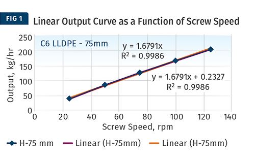
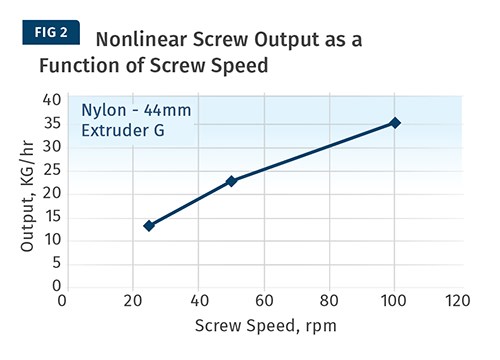
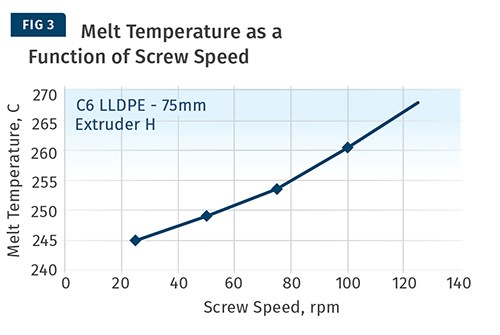
So how do you check an extrusion system for design rate compliance? First inspect and measure the screw profile, compare it with the screw design to make sure it was manufactured properly. It’s your screw; you can and should have a drawing of it from the supplier. Measure output (Figs. 1 and 2), melt temperature (Fig. 3), and melt-temperature stability, motor power, and pressure stability as a function of screw speed, for at least one set of barrel temperatures. Output should be linear with screw speed (Fig. 1). An output curve with a decreasing slope vs. screw speed (as in Fig. 2) indicates a screw that is losing performance with speed and should be replaced.
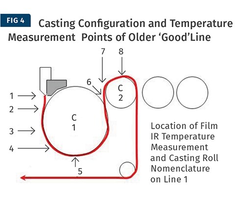
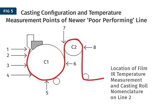
Quenching capacity and/or heat-transfer coefficients can be measured several ways during film processing. Points of interest will be water flow rate, water temperature rise across the roll, and final film temperature. Film properties will be dependent on the thermal history of the polymer, so if you are adding capacity with the new line you will have to measure its thermal history and compare it with the first line to get the same product performance.
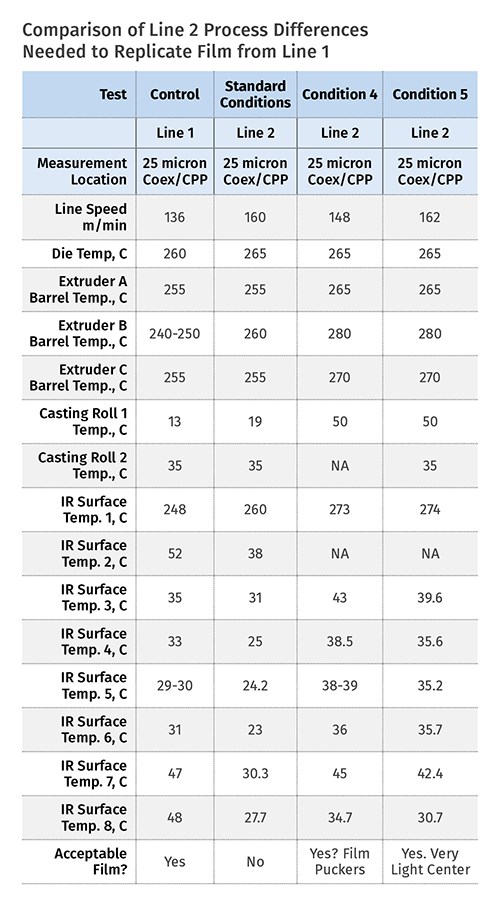
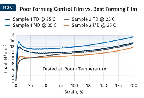
For instance, Figs. 4 and 5 show two lines with the “same” quenching configuration purchased a few years apart. With the same setpoints, the original line yields acceptable product, but the new line, specified to be the same as the old line, gives a considerably different tensile property (Fig. 6) and does not perform as the same film design from Line 1.
Table 1 details the film temperatures measured on each line with an IR gun at the same line speed and roll-temperature settings. It’s clear that even though the two lines have essentially the same quench-roll configuration, and use the same roll-temperature set points, the thermal history of each film is completely different. This yields films with different tensile properties, shown in Fig. 6, which give different performance in the application.
In order to make the same film as from the old line on the new one, new process settings are needed to obtain the same film temperature profile, or thermal history. The differences are likely due to changes (either better or worse) in the heat transfer in the newer rolls versus the older rolls. For even though the quench rolls are “the same” in terms of outer dimensions and surface finish, the water flow rates, internal flow channel dimensions, etc. are most likely very different in the two rolls, resulting in very different thermal histories for the two films. It is not the roll shape and finish that control film properties but the thermal history that the polymer film layers experience. To make the two lines “the same” thermally, it is necessary to change the roll setpoints to match the thermal profile in the film or to match roll heat-transfer coefficients.
Web handling and winding performance are a little harder to measure, but the transport of film without wrinkles and creases or stretching are key items. For winding there will be a film formulation component that cannot be ignored; but overall for winding, use roll density (kg/m3). However, the real proof of the winding process is slitting yield.
After performing all of the line-component checks, it’s time start production. Focus on getting the line up to speed and begin adjusting settings to optimize film properties and quality. The first stage of the start-up will be to get the film gauge flat by setting the average die gap and edge-pinning systems to obtain a stable edge profiles and film formation while adjusting the die. For coextrusion systems, adjust extruder temperatures to control melt viscosity to eliminate any melt disturbance that might be present. Knowing melt temperature as a function of output rate will be critical to maintaining acceptable coextrusion stability.
With film on the winder, the performance of the line can be fine-tuned and film thermal history and properties optimized. If the film is not on the winder, it is not possible to fine-tune the film properties with the process. Optimizing film properties may take the form of additive concentration changes for surface properties or refinements of barrier layer thicknesses for barrier properties. Mechanical properties will be controlled primarily by polymer selection and extrusion and casting conditions.
Overall, if we concentrate on the first four steps, the last step should be easy. The real goal of the first four steps is to permit the routine formation of film and having it on the winder so that the properties can be refined. In the few cases where a new line start-up does not go well, it is generally the case that one or more of the first four steps were not done or, worse, that there was no clear conception of what the line was supposed to do and the line has not been designed to optimize the production of the desired product.
By the way, when you recondition an older line to increase productivity or to add capability, such as going from three to seven layers, or install a larger or additional extruder(s) or quenching system, you should expect to do the same sort of five-step checks when you are ready to restart.
Also, if you have purchased an existing line and are moving it to a new location, prepare to do the same work as if it were a new line (but perhaps without documentation). If you have done this to save money, don’t be surprised to find out that reconditioning older equipment or integrating older equipment into a newer line can sometimes cost as much as buying new and, if it integrates poorly, perhaps cost more in lost productivity. This sort of work requires even more diligence from your engineering, installation, and start-up team.
Related Content
Flexible-Film Processor Optimizes All-PE Food Packaging
Tobe Packaging’s breakthrough was to create its Ecolefin PE multilayer film that could be applied with a specialized barrier coating.
Read MoreNew Blown-Film Cooling Technologies Set to Debut at NPE2024
Cooling specialist Addex to roll out new auto-profiling air ring for rotating dies, and new single-plenum air ring.
Read MoreDeflection Elbows Eliminate Streamers for Large Film Processor
New elbows eliminate troublesome streamers to increase productivity at leading blown film processor.
Read MoreBreaking News From NPE2024
Here is a firsthand report of news in injection molding, extrusion, blow molding and recycling not previously covered.
Read MoreRead Next
People 4.0 – How to Get Buy-In from Your Staff for Industry 4.0 Systems
Implementing a production monitoring system as the foundation of a ‘smart factory’ is about integrating people with new technology as much as it is about integrating machines and computers. Here are tips from a company that has gone through the process.
Read MoreLead the Conversation, Change the Conversation
Coverage of single-use plastics can be both misleading and demoralizing. Here are 10 tips for changing the perception of the plastics industry at your company and in your community.
Read More
