Extrusion: Follow These Tips to Get Profile Die Design Just Right
Calculating polymer flow is fairly straightforward when designing a die for a simple round profile, but as the shapes get more complicated these calculations can get extremely challenging. Here’s what you need to consider.
Share
I have found that a lot of experienced extrusion operators—especially those with limited background in polymer rheology—tend to think the material “slides” through the die to form its final shape. In fact, the polymer should adhere firmly to the die walls, as slips result in melt fracture. That effect has a considerable influence on the die design and it’s important to understand this when troubleshooting die performance.
Once the polymer exits the extruder and enters the die it sticks quite firmly to the die walls and is sheared in the die openings as pressure from the screw or melt pump forces it through the die. Calculating polymer flow is not all that difficult when designing a die for a simple round profile, but as the shapes get more complicated these calculations can get extremely challenging. Just moving to a simple rectangle makes things more complex.
A circular profile tends to just get a little smaller than the die cross-section (neglecting polymer swell) because of the polymer adhering to the wall—but the shape does not change. On the other hand, with a simple rectangular profile the square corners will not fill out because the additional surface area in the corners causes a reduction in flow. This tends to round the corners. The shear stress in the polymer shape is always zero in its exact center of flow, which may or may not be the center of the part (except in the simplest shapes). The maximum shear stress occurs at the die wall, and shear stress increases proportionally with the distance from the center point of flow. That variation in shear stress alone develops a slight difference in viscosity due to the changing shear. The more complex the profile, the more complex the effects.
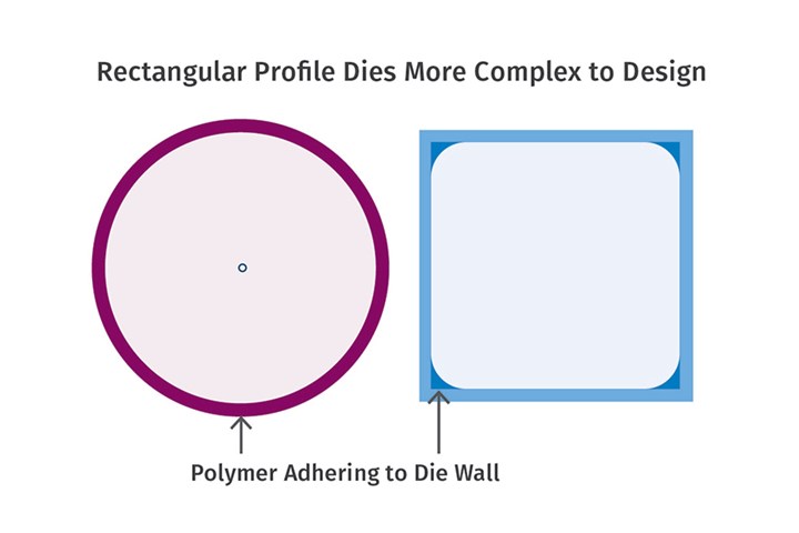
FIG 1 A circular profile tends to just get a little smaller than the die cross section (neglecting polymer swell) because of the polymer adhering to the wall—but the shape does not change. But with a simple rectangular profile the square corners won’t fill out because the additional surface area in the corners causes a reduction in flow. This tends to round the corners.
Thus, as the die becomes more complicated, the variations in flow become more complex and the die internals often do not look that much like the final part. Note the rounded corners in the relatively simple square profile in Fig. 1. For that profile, the die had to be designed with additional space for polymer to flow into all the corners as the part moves through the die.
Each surface of the die also needs to be uniformly heated so that the viscosity along the walls provides for the same pressure drop to match the other legs, so that the profile stays “square” exiting the die. Any unbalanced heating of the die can distort the shape by varying the viscosity near the die wall. This occurs even in simple dies such as one in Fig. 1, but it becomes much more pronounced in more complex profile dies where the shape is more irregular (see Fig. 2).
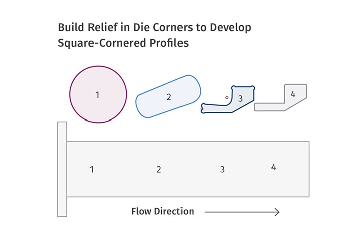
FIG 2 The sections labeled 1 to 4 show how the shape of the die channel would change from extruder exit on the left to die exit on the right (with continuous transitions in between). Relief in the corners is needed to develop relatively square corners.
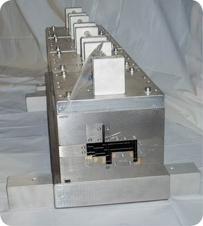
With a little more complicated (but still relatively simple) profile these differences can be seen. The sections labeled 1-4 show what the shape of the die would be from the extruder exit to the die exit. Between each section there are continuous transitions. Relief in the corners of the die is necessary to develop relatively square corners, both inside and out. The size of relief will vary with the polymer viscosity and the pressure drop in the leg.
Fortunately, there are now a number of very good simulation programs to assist in die design, saving hundreds of hours in calculating all the variables in a complex profile. But the important point is that the internal die design is not likely to mimic the final profile shape, except very near the exit, and there is no sliding/shaping like with a liquid in a shaped orifice.
Even though you may not design your own dies, having a basic understanding of die flow will help when problems arise with existing tooling. First, look for obvious changes in melt temperature and die-heating uniformity. Surprisingly, even changes in output can affect the shape of the profile if everything else seems correct. A change in output affects melt viscosity due to a change in melt temperature, and that can affect the balance of flow in various legs of a complex profile.
ABOUT THE AUTHOR: Jim Frankland is a mechanical engineer who has been involved in all types of extrusion processing for more than 50 years. He is now president of Frankland Plastics Consulting, LLC. Contact jim.frankland@comcast.net or (724)651-9196.
Related Content
Improving Twin-Screw Compounding of Reinforced Polyolefins
Compounders face a number of processing challenges when incorporating a high loading of low-bulk-density mineral filler into polyolefins. Here are some possible solutions.
Read MoreUnderstanding Melting in Single-Screw Extruders
You can better visualize the melting process by “flipping” the observation point so the barrel appears to be turning clockwise around a stationary screw.
Read MoreHow to Select the Right Cooling Stack for Sheet
First, remember there is no universal cooling-roll stack. And be sure to take into account the specific heat of the polymer you are processing.
Read MoreFundamentals of Polyethylene – Part 6: PE Performance
Don’t assume you know everything there is to know about PE because it’s been around so long. Here is yet another example of how the performance of PE is influenced by molecular weight and density.
Read MoreRead Next
How To Size & Calibrate Profile Parts
Doing it right is critical to maintaining profile dimensions.
Read More
.jpg;width=70;height=70;mode=crop)
