LSR Part III-- Choosing a Mixing/Metering System
Liquid silicone rubber (LSR ) is a two component reactive chemical with a viscous, paste-like consistency.
Liquid silicone rubber (LSR ) is a two component reactive chemical with a viscous, paste-like consistency. The A & B components are shipped to the user in separate containers, either 5-gal or 20-liter pails, 55-gal or 200-liter drums, or small disposable plastic cartridges for some medical-grade silicones.
A & B components are mixed in a 1:1 ratio to produce the reaction, accelerated by heat, that changes the liquids to a solid rubber. The meter-mix machine is the first mechanical device in the molding process, followed by the injection molding machine and injection tooling. Here’s what you should know about this critical component. (Part I of this series, in June 2010, covered LSR materials. Part II, in Aug. 2010, covered the injection machine. Part IV will cover tooling.)
ROLE OF THE METER-MIX SYSTEM
The primary function of the meter-mix device is ratio control—i.e., to deliver an accurately metered 1:1 (or 50:50) ratio of A & B materials to the injection machine’s feed throat. Liquid silicones are designed to produce good cured properties (such as durometer and tear and tensile strengths) even when metered slightly off-ratio. For example the cured properties typically will be the same at 52:48 or 48:52 ratio as at the desired 50:50.
However, the meter-mix machine must be capable of producing the specified 50:50 ratio within ±1%. High accuracy is needed both for insurance against mixing off-tolerance product and for reasons of economy. Since the A & B components are purchased in equal volumes, any amount of one component left over because of inaccurate metering is wasted. Variable-ratio controls are available to make up for differences in viscosity between A & B components.
The second key function of the meter-mix machine is to maintain a clean product. The LSR molding process is inherently clean because the chemicals are sealed in a closed system. Ambient air with its accompanying dust and moisture does not contact the product from the time drums are installed on the meter-mix machine until finished parts are removed from the mold.
Therefore it is important that the meter-mix machine not add contaminants. Metal parts must be corrosion resistant to prevent rust from forming. For medical applications, the metal that contacts the material should be made of sanitary grades such as stainless steel. Material hoses should be lined with PTFE or nylon since conventional rubber-lined hydraulic hoses may contain sulfur, which will contaminate the silicone and may inhibit cure. PTFE-lined hoses are especially desirable for medical applications.
Silicone purity is especially important when molding implantable medical parts or parts that contact blood or drugs in their end use. Industrial parts also benefit from a “clean” system because contaminants often reduce the physical properties of the cured rubber.
A third function of the meter-mix system is to introduce minor components, such as colorants, biocides, or self-bleeding oils. The meter-mix machine should have the ability to add third and fourth components when needed, at the desired ratios and accuracy.
Fourth, the meter-mix machine must thoroughly mix the A & B components as well as the smaller amounts of third and fourth streams. Because of the various styles of injection molding machines, the amount of mixing required varies.
Fifth, the meter-mix machine must supply the mixed silicone at a uniform pressure to the injection barrel. A consistent supply pressure will fill the barrel to the same volume and pressure on each cycle, resulting in shot-size repeatability. This is especially important because of the compressibility of liquid silicone.
BASIC COMPONENTS OF THE MACHINE
Dispensing high-viscosity LSR material requires use of a ram and follow-plate assembly. The ram, pneumatic or hydraulic powered, provides the pressure needed to force the follow plate into the container and pressurize the silicone under the plate. The pressure forces the viscous silicone to the flow channel at the center of the plate and aids in filling the pump. The seals on the follow plate prevent leakage and stop contaminants from entering the container.
Drum transfer pumps, double- or single-acting, may be used to do the actual metering or to supply material to a separate metering pump. The metering-pump drive cylinder(s) may be powered by air or hydraulics. The ratio of the cylinder to pump area should provide up to 4000 psi pressure to force the viscous silicone through the hoses and manifold/mixer assembly to the injection barrel.
Hoses for the A & B and other components carry the fluids from the metering pumps to a manifold assembly. The manifold incorporates check valves for each fluid to prevent backflow, which could leave cured rubber in the hoses. The check valves also isolate manifold pressure from the individual pump pressures, which is useful in monitoring pump performance.
A static mixer should be included in the system. Although the injection screw does some mixing, it’s best to provide a good mix prior to the screw. Third and fourth streams also may require additional mixing.
Water-cooling jackets (typically 65-75 F) are available for all components in the mixed material stream except the screen pack.
TWO TYPES OF MACHINES
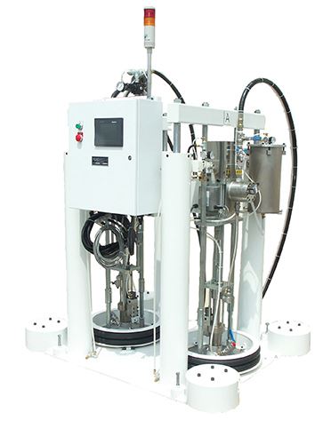
There are two general types of meter-mix machines: Direct from the Drum and Transfer & Meter. In a Direct from the Drum machine, the A & B metering pumps are mounted within the ram and follow-plate assemblies. The metering pump draws fluids from the drum and meters them through hoses to the manifold and mixer assembly.
The only wetted components are the follow plates, pumps, hoses, manifold, mixer, and possibly precision flowmeters. This type of machine has the smallest number of wetted components to clean when changing materials. Most dedicated 5-gal machines are of this type, since they are often used in short-run applications.
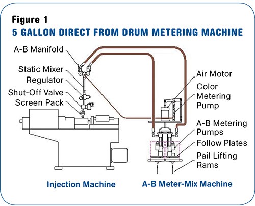
Whether using 5- or 55-gal machines, the Direct from the Drum design affords the fastest and most economical material changes. In its simplest form, identical A & B metering pumps are joined together mechanically and driven by a single motor to produce a 1:1 ratio (Fig. 1).
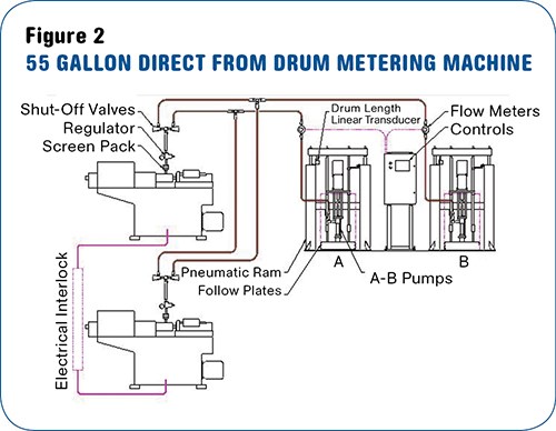
Figure 2 illustrates a more capable Direct from the Drum system. A & B ratio control is achieved by pumping fluids through precision flowmeters. Signals from the flowmeters are processed by a PLC to maintain 1:1 ratio or a preselected off-ratio. Ratio control is closed-loop since the control circuit adjusts pump speeds for actual flow sensed by the flowmeters.
Addition of linear transducers to sense follow-plate position in the drums provides data on A & B component inventory. That data is used to make minor ratio adjustments in order to use all of the silicone in both drums and to monitor usage and delivery.
Another version of the Direct from the Drum system does not use precision flowmeters. In place of meters, optical encoders are installed on each pump to track its stroke. The control system then prompts the A & B pumps to cycle through identical strokes to achieve 1:1 ratio or a desired off-ratio. This system is good for abrasive silicones, which wear flowmeters too quickly.
Direct from the Drum machines have two limitations. One is that mixed-material pressure at the feed throat varies as the pumps cycle up and down. An additional device called a material pressure regulator, is required to deliver a constant feed-throat pressure.
Second, when feeding two injection machines with one meter-mix system, the presses must be interlocked so that only one can refill at a time. The metering machine cannot ensure ratio at two delivery points simultaneously. Some productivity loss can occur if one injection press must wait to refill.
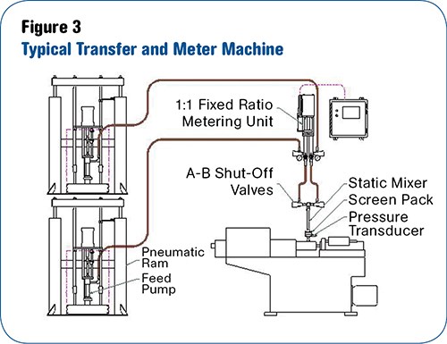
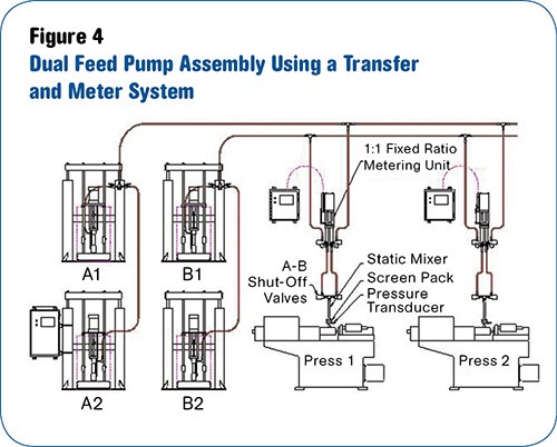
In the second meter-mix design, a Transfer & Meter system, transfer pumps instead of metering pumps are located within the ram/follow-plate assemblies. They supply A & B components to a separate metering unit, usually located beside the press. The metering unit is a dual set of single-acting piston pumps, both driven by a common air cylinder or servo motor to deliver a fixed 1:1 ratio. The metering chambers fill on the retract stroke and dispense on the extend stroke. Because the metering pumps are so mechanically simple, they produce the same pressure on each extend stroke, unlike the more complex metering pumps used in Direct from the Drum systems. With the proper controls, mixed material pressure at the feed throat will repeat within 1 to 2 atmospheres, sufficient for any molding process. A material pressure regulator is not required, saving maintenance and cleaning when changing compounds. Feed-throat pressure is programmable on the operator interface of Transfer & Meter systems; it’s mechanically adjustable at the regulator on Direct from the Drum machines.
When production requires two or more presses to operate from one set of transfer pumps, a metering unit is placed at each press. Since each metering unit is independent, the presses do not need to be electrically interlocked. If both barrels fill at the same time, mix ratio will be accurate at both locations.
Figure 4 illustrates Transfer & Meter units with automatic drum change. Operators do not need to be present to change drums when one set empties. This eliminates drum-change downtime and facilitates “lights out” molding.
Transfer & Meter systems are generally used for longer runs. Material changes take longer and waste more silicone than Direct from the Drum systems, making the direct system more practical for short runs.
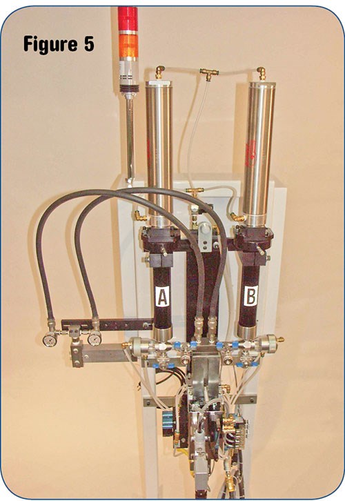
An exception to the rule is shown in Fig. 5. Although the micro-meter is a Transfer & Meter style machine, it is very small and can be cleaned to change compounds quickly with minimum waste. The unit shown in Fig. 5 is mounted on a stand along with the control panel and is located next to the injection press with short hose running to the barrel stack (manifold & static mixer). In place of feed pumps, A & B components are fed from disposable cartridges, normally holding 12 or 20 oz. The micro-meter is especially suited for molding costly implant-grade medical silicone and for prototypes or very small parts.
Some grades of LSR can be purchased pre-packaged in 12- or 20-oz tubes. For silicone received in 5-gal or 20-liter pails, cartridge-filling equipment is available.
ADDING PIGMENT AND/OR ADDITIVES
Pigments and self-bleeding fluids are some of the most common third-stream additives. Loading is usually between 0.5% and 5% of the A & B volume. Metering accuracy required is ±0.2%.
Two types of additive metering pumps are used. Figure 1 illustrates a mechanical slave pump where the stroke length of the pumps is manually adjusted to change metering percentage. The pump and feed pot are located on the A-B metering unit and color is carried through a hose to the mix manifold.
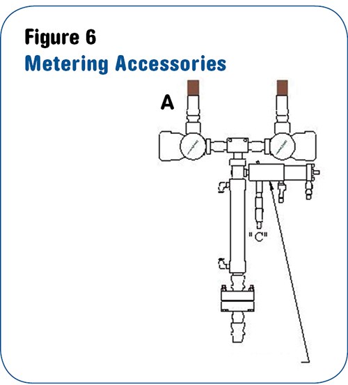
The second type of pump is called a color injector or third-stream injector, illustrated in Fig. 6. It is mechanically independent from the A-B meter and is mounted at the static mixer. The injector uses a small-diameter plunger powered by an air cylinder to inject small, precise shots of pigment into the mixer. The size and frequency of the shots relative to A-B volume determines pigment percentage.
The operator enters injector shot size and desired color percentage on the machine interface screen rather than making mechanical adjustments as with the slave-driven pump. The controls on either Direct from the Drum or Transfer & Meter machines will accommodate the injector.
In addition to ease of ratio change, the injectors are easier to clean for color changes. Also, when feeding two presses, the slave-driven color pump must deliver the same color to both presses. The injectors can deliver a different color to each press, since they are mechanically independent from the A-B meter. It is also possible to add a color and another additive with the addition of a second injector and supply vessel.
Pigment supply devices range from 2.5-oz cartridges on the micro-meter to 55-gal pumps on large systems. Most systems use 1- to 10-gal pressure feed tanks.
Related Content
For Extrusion and Injection-Blow Molders, Numerous Upgrades in Machines and Services
Uniloy is revising its machinery lines across the board and strengthening after-sales services in tooling maintenance, spare parts and tech service.
Read MoreLatest Data on Bottled Water Shows Continued Strong Growth
Bottled water’s volume surpassed soft drinks for the first time in 2016 and has done so every year since.
Read More‘Monomaterial’ Trend in Packaging and Beyond Will Only Thrive
In terms of sustainability measures, monomaterial structures are already making good headway and will evolve even further.
Read MoreConsistent Shots for Consistent Shots
An integral supplier in the effort to fast-track COVID-19 vaccine deployment, Retractable Technologies turned to Arburg and its PressurePilot technology to help deliver more than 500 million syringes during the pandemic.
Read MoreRead Next
Getting Into LSR: Part II--Chosing an Injection Machine
The criteria for selecting a liquid silicone rubber injection molding machine are very similar to selecting a machine for standard thermoplastic injection molding, with several key differences.
Read MoreGetting Started in LSR: Understanding the Materials, Part I
Liquid silicone rubber (LSR) injection molding is a long established process but it is enjoying an upsurge in interest for medical, automotive, infant care, and general industrial applications.
Read MoreSee Recyclers Close the Loop on Trade Show Production Scrap at NPE2024
A collaboration between show organizer PLASTICS, recycler CPR and size reduction experts WEIMA and Conair recovered and recycled all production scrap at NPE2024.
Read More
