Improve The Cooling Performance Of Your Molds
Need to figure out your mold-cooling energy requirements for the various polymers you run? What about sizing cooling circuits so they provide adequate cooling capacity? Learn the tricks of the trade here.
The first law of thermodynamics states that energy cannot be created or destroyed, but only transferred from one place to another. If you think of an injection mold as a closed thermodynamic system, you can account for the energy entering and leaving the system. A shot of molten plastic injected into a mold is the energy input, and energy leaves by various mechanisms. Some of the energy (heat) is carried away in the ejected parts and some is removed by the cooling system. It is less obvious, but some energy will also go into the surrounding environment when a mold is heated substantially above room temperature.
For simplicity, we can ignore any heat loss due to elevated mold temperature. This leaves us with three relatively simple tasks to quantify the energy flow and estimate cooling requirements, assuming a traditional water-circulation cooling system:
1. Understand the thermal properties of polymers and learn the method for calculating energy values and flow for both amorphous and semi-crystalline materials.
2. Calculate the (cooling) energy that must be removed from the molded parts to change the temperature from the processing (melt) temperature to a safe ejection temperature.
3. Using the cooling energy requirement as a starting place, determine the diameter and length of cooling circuits, the coolant ∆T value, and the coolant flow rate required to be turbulent and to remove the required amount of heat (energy).
Polymer Thermal Properties
For a discussion of polymers and energy, we must employ a system of units so we can quantify amounts of energy. The energy unit commonly used in North America is the British Thermal Unit or BTU, defined as the amount of energy required to heat 1 lb of distilled water by 1 °F. We can say, then, that distilled water has a heat capacity, commonly designated CP, of 1 BTU/lb-°F. Other materials have their own unique heat-capacity value that quantifies how much heat (energy) in BTUs must be added to change the temperature of a pound of that substance by 1° F. The accompanying equation provides values of CP for common materials of interest to us. Choosing the letter E to represent energy:
E = W x CP x ∆T in BTU, where
W = weight of material in lb
CP = Heat Capacity in BTU/lb-°F, and
∆T = change in temperature, °F.
For example, let’s say we are molding a part weighing 0.45 lb using ABS, an amorphous material. Molten ABS is injected into the mold at a processing temperature of 464 F and the molded parts are ejected at 212 F, the ejection temperature. We want to know how much energy is required to cool this shot—that is, to change the temperature from 464 F to 212 F. Referring to the table, we note that the heat capacity of ABS is 0.34 BTU/lb-°F and therefore:
E = 0.45 lb x 0.34 BTU/lb-°F x (464-212) °F = 0.45 x 0.34 x 252 = 38.56 BTU
We have shown how to calculate the cooling energy for one shot. Next we need to determine a cooling or energy flow rate, represented by the letter Q. For this we must take into account the rate at which the material flows through the mold. This is done simply by calculating shots per hour (SPH) and multiplying that times the BTUs per shot. SPH is calculated by dividing the number of seconds in an hour (60 x 60) by the cycle time in seconds. For a 15-sec cycle: SPH = 3600/15 = 240 shots/hr. Thus, the energy flow required to cool the ABS part from our example above is:
Q = SPH x BTU/shot = 240 x 38.56 = 9254.4 BTU/hr
For semi-crystalline resins, there is an additional factor that figures into the energy calculation. Unlike amorphous polymers such as ABS, semi-crystalline polymers have regions of highly organized molecules called crystallites that require extra energy to change from the crystalline state to an amorphous state during melting. The crystalline structures re-establish during cooling and an equal amount of extra energy must be removed to reverse the change in state. The extra (heat) energy is called latent heat of crystallization. Amorphous polymers do not have the crystalline structures and thus do not have a latent heat value.
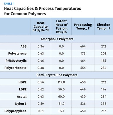
Each semi-crystalline polymer has a unique value for the latent heat per pound of material. Latent heat can therefore be defined as the amount of heat per pound of material required to break down the crystalline structure during melting or to re-establish the crystalline structure during cooling. Values for latent heat are expressed in BTU/lb. Table 1 shows values for both heat capacity and latent heat for some common semi-crystalline materials.
The energy calculation for semi-crystalline materials is similar to the ABS example above, except that we must also account for the latent heat. We will use polypropylene to demonstrate the method.
First, calculate energy per shot assuming a shot weight of 0.30 lb, CP of 0.61 BTU/lb-°F, ∆T of (450-212), and a latent heat value (HL) of 89.1 BTU/lb.
E/shot = W x ((CP x ∆T) + HL) or:
E/shot = 0.30 x ((0.61 x 238) + 89.1) = 0.30 x (145.2 + 89.1) = 0.30 x 234.3 = 70.3 BTU/shot.
Assuming a cycle time of 8 sec, SPH=3600/8 = 450. With this value we can calculate that the energy flow to cool this process:
Q=70.3 BTU/shot x 450 SPH = 31,635 BTU/hr.
Notice that the cooling energy requirement in this example is quite large relative to the amorphous ABS part, despite the smaller PP part weight, due to the latent-heat component and faster cycle.
Cooling by Water Circulation
One primary function of an injection mold is to be a heat exchanger. The heat input is the molten polymer injected at regular intervals. Sufficient heat must be removed from the mold so parts are cooled to a safe ejection temperature. This is normally accomplished by circulation of a temperature-controlled liquid coolant (usually water) with the goal of maintaining a steady mold temperature suitable for cooling the parts. As water flows through a cooling circuit its temperature gradually increases and thus carries away heat from the molded parts.
Knowing the ∆T of the water as it flows through the mold and the flow rate, we can determine the energy flow rate, QW, for a particular cooling circuit:
QW = ∆T x GPM x 60 min/hr x 8.34 lb/gal x 1 BTU/lb-°F.
QW = ∆T x GPM x 500.4.
Let’s assume, for example, a ∆T of 2.8 °F and a flow rate of 0.85 GPM:
QW = 2.8 x .85 x 500.4 = 1190.95 BTU/hr
We can also rearrange this expression to calculate a GPM requirement, assuming we already know how much heat we need to remove and assuming a value for ∆T. This expression would be:
GPM = QW /(∆T x 500.4).
For example, let’s say we have determined that for a single-cavity mold with a single cooling circuit on the B-side that we need to remove 1800 BTU/hr. Next, assume for this cooling circuit that:
∆T = 3.5 °F.
GPM = 1800/(3.5 x 500.4)=1.03 GPM.
These examples illustrate the relatively simple calculation methods for determining the cooling capacity of an existing circuit and for determining the flow rate needed to remove a certain amount of heat based on a certain value of ∆T. The techniques we have so far demonstrated are the basic tools for evaluating existing cooling circuits and for designing new circuits. But an important question remains unanswered: What value of ∆T should we use?
Some molders have conducted internal studies of coolant ∆T in actual production conditions. With this method one can build a database of ∆T values for real parts, based on actual molding parameters, including material, process temperatures, shot weight, coolant flow rate, and shots per hour. This is a great way to improve your cooling design capability.
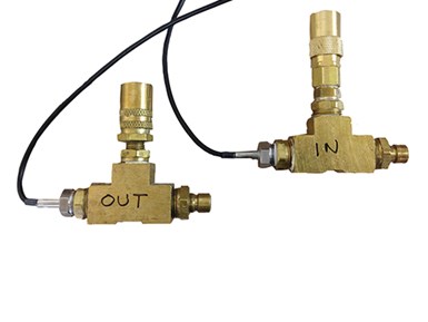
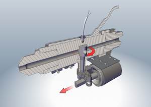
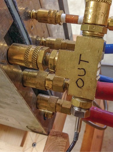
Measuring ∆T through a cooling circuit requires extremely accurate sensors, since the temperature change can be as low as a degree or two. Measuring with a pair of ultra-precision immersion-style RTDs and a hand-held, dual-channel reader is a good method. The sensors can be mounted in a pair of tees with quick-connect fittings on the other ports, creating a convenient way to tap into cooling circuits for measuring ∆T (see photo).
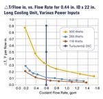
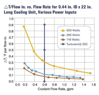
Another approach is to use ∆T values developed in a laboratory. Burger & Brown Engineering, Inc. conducts research on ∆T values vs. heat input using its electrically heated mold simulators. The company has done trials with a round core and flat mold plates. In these trials, we used constant coolant flow rates well above the turbulent-flow transition. We varied the heat input to the mold and measured the coolant-temperature response. Heat input is related to cycle time, material type, and shot size. From our data, we calculated values of ∆T per inch of cooling-circuit length. A graph of the results is shown in Fig. 1. While limited in scope, this data provides a rational and useful basis for estimating ∆T when designing new cooling circuits.
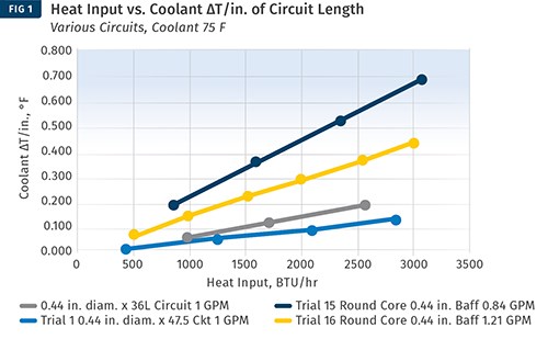
Here, trials of ∆T vs. heat input were conducted using Burger & Brown’s electrically heated mold simulators. Constant coolant flow rates well above the turbulent-flow transition were used. The heat input to the mold was varied, and the coolant temperature response was measured. This permitted values of ∆T/in. of cooling-circuit length to be calculated. This data provides a rational and useful basis for estimating ∆T when designing new cooling circuits.
The following example will illustrate a method for designing a cooling circuit for a mold core running a 5-in. diam., 0.050-in. thick round PP cap. Part weight is 0.043 lb and cycle time is 12 sec. Melt temperature is 500 F and part ejection temperature is 180 F, yielding a required cooling-temperature change of 320 °F. With these values and with PP thermal properties from the table, we can calculate the cooling energy required for this part using the following steps:
1) SPH = 3600/12 = 300
2) W (lb of material processed/hr) = 0.043 lb/shot x 300 SPH = 12.9 lb/hr
3) Cooling energy per part, QCooling = W x ((0.61 BTU/lb-°F
x 320 °F) + 89.1 BTU/lb) = 12.9 x (195.2 + 89.1) = 12.9 x 284.3
= 3667.5 BTU/hr.
4) Next, we must decide how much of the cooling energy to allocate to the B-half of the mold. Unless we have data available from other existing molds, this allocation might be estimated using mold simulation software or by a seat-of-the-pants method. For our example let’s assign 55% to the B-side using the rationale that the part cools a little longer on the B-side. Thus, the core cooling requirement is:
QCore =0.55 x 3667.5 = 2017 BTU/hr.
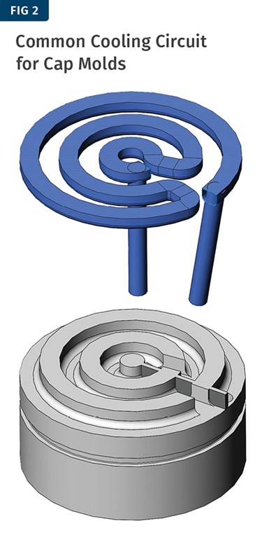
Now we are ready to think about the possible geometry of a cooling circuit for our core. Figure 2 shows a common circuit layout used with cap molds. For this circuit, the effective cooling length is 23 in. with an effective diameter of 0.335 in.
Referring to Fig. 1, we can select a value for ∆T/in. corresponding to our heat input of around 2000 BTU/hr. This cooling design more closely resembles a flat plate and it puts the water fairly close to the molding surface, perhaps 0.63-0.75 in. The concentric rings provide a circuit with substantial length, which would push the ΔT value higher. Finally, the energy density is fairly high—meaning the BTU/hr/in.² of molded part area. It would be reasonable to choose a mid-range ΔT/in. value of 0.20. Then we can do the calculation to see if it yields a reasonable coolant flow-rate requirement. QW is the energy that must be carried away by the water:
GPM = QW / (∆T x 500.4).
ΔT = 0.20 °F x Circuit Length or 0.20 x 23 in. = 4.6 °F.
GPM required = 2000/(4.6 x 500.4) = 2000/2302 = 0.87 GPM.
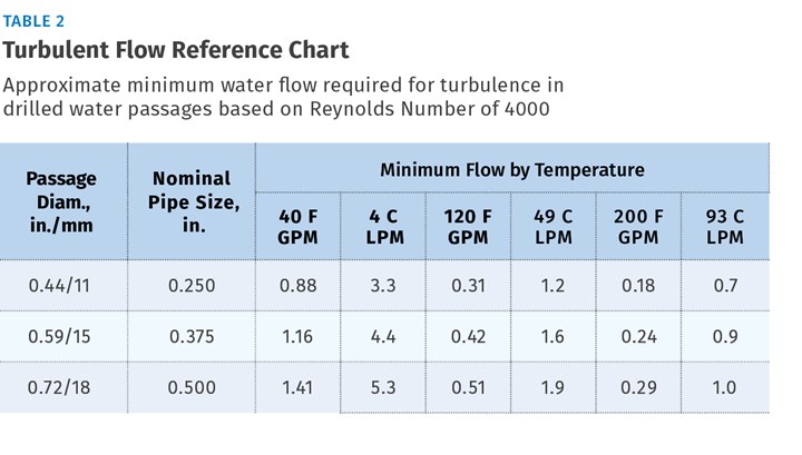
Referring to Table 2 and extrapolating a value for the effective circuit diameter of 0.335 in., our 0.87 GPM seems sufficient to provide turbulence, even at a water temperature of 40 F.
The foundation of designing cooling circuits is a good ∆T estimate. Many factors affect this value. Coolant temperature increases as it flows through the circuit, based on the rate of energy input from the shot, flow rate of the coolant, length and diameter of the circuit, the material used to build the mold, and the proximity of the circuit to the molding surfaces. Processors can conduct internal studies of cooling circuit ∆T to develop a sound basis for future designs.
ABOUT THE AUTHOR: PHILIP BURGER
Phil Burger, P.E., founded Burger & Brown Engineering, Inc. in 1978 and served as president until 2005. Based in Grandview, Mo., Burger & Brown manufactures engineered products related to mold cooling and in-mold sensing and holds 10 patents for its products. Burger currently works part-time for the firm and most recently developed an educational program called Scientific Cooling, launched in October 2013. Contact: (816) 878-6675; trumpetman44@hotmail.com; smartflow-usa.com.
Related Content
Fundamentals of Polyethylene – Part 6: PE Performance
Don’t assume you know everything there is to know about PE because it’s been around so long. Here is yet another example of how the performance of PE is influenced by molecular weight and density.
Read MoreOptimizing Pack & Hold Times for Hot-Runner & Valve-Gated Molds
Using scientific procedures will help you put an end to all that time-consuming trial and error. Part 1 of 2.
Read MoreKnow Your Options in Injection Machine Nozzles
Improvements in nozzle design in recent years overcome some of the limitations of previous filter, mixing, and shut-off nozzles.
Read MoreGot Streaks or Black Specs? Here’s How to Find and Fix Them
Determining the source of streaking or contamination in your molded parts is a critical step in perfecting your purging procedures ultimately saving you time and money.
Read MoreRead Next
Leverage Your Cooling Power
You can predict the amount of heat you'll need to remove from parts before ejection with reasonable accuracy if you know polymer thermal properties and certain other rules of thumb.
Read MoreBeyond Prototypes: 8 Ways the Plastics Industry Is Using 3D Printing
Plastics processors are finding applications for 3D printing around the plant and across the supply chain. Here are 8 examples to look for at NPE2024.
Read More
