Used in a wide range of medical devices worldwide—including drug-delivery devices, orthoscopic surgical instruments, chest drains, and catheters—ultrasonic welding is assuming a growing role in the medical industry as devices become more complex and sophisticated. These devices are increasingly composed of plastic parts that are smaller and lighter and may contain other components that place additional requirements on the joining process. While more traditional fastening methods can be considered, processors are finding that ultrasonic welding offers significant advantages.
To meet the high standards of the medical industry, ultrasonic welding manufacturers are developing unique technology that meets all the requirements for repeatable, and consistent welds in these smaller and more intricate systems, including technology for cleanrooms. This means the highest levels of quality for welding results, well-chosen materials for tools, and absolute process control thanks to recording software for validation purposes and quality-assurance monitoring. Expert project management is based on certifications in accordance with ISO 13485 and ISO 9001.
Processors are finding that ultrasonic welding offers significant advantages.
Increasing demand for faster deliveries and highly complex welding applications has led welding manufacturers to bring on new capacity. Suppliers have transferred ultrasonic tooling in-house in order to assume complete control of documentation, testing, and other key program functions for its medical customers.
Materials, Part Design Play Key Roles
Among the key technical considerations in joining of medical devices are materials, process parameters, and part design. Amorphous materials such as ABS, PS, and PC tend to be much easier to weld due to their melt-point characteristics. They tend to soften and gradually pass through their rigid state to the glass transition, then into a rubbery state followed by the true molten state. Their solidification is also gradual.
Meanwhile, semicrystalline materials such as nylon, PP, and PE have a very sharp melting point, which requires more energy to achieve. The solidification is just as sharp (Fig. 1).
After identifying the material for the application, the parts need to be designed with the proper joint. such as a shear joint for a hermetic seal after welding, or a simple energy director to bond the two parts together (Fig. 2). The ultrasonic welding supplier can evaluate the appropriate ultrasonic tooling design for the application based on the material to be used and the function of the end product.
Ultrasonic welding of today’s complex medical devices with their many internal components and ergonomic design requirements for the comfort of the doctor or surgeon also makes the tooling more complex. Applications need not only to fit the parts but have the right amount of output amplitude to allow the material to melt.
Troubleshooting Horn Issues
Figure 3 shows a typical complex ultrasonic horn consisting of a large mother horn and 13 extender horns (commonly known as a composite horn). The extender horns are contour milled to match the part detail and each extender is timed into the correct position to allow for proper contact on the part.
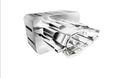
FIG 3 This multi-element horn, comprised of a mother horn and several extenders, is designed to weld a medical stethoscope.
There are numerous troubleshooting issues that could arise when utilizing this type of horn for medical parts:
▪ One common horn issue is marking on the parts, which could range from small scuff marks to material discoloration. Part marking could be the result of dimensional changes in the molded parts or the addition of additives in the molding process. Processors are advised to check part dimensions and molding conditions.
▪ Another issue could be part-to-horn alignment. For all horns, the alignment between the horn and the part and fixture are critical. If the extenders on the composite horn are out of alignment, tool realignment could be necessary. Check the extenders and make the proper adjustment.
▪ Horn face damage caused by wear or damage to the face contacting the fixture with no part present can also cause marking or component failure. Uncoated (raw) aluminum horns will release aluminum oxide and cause black residue on the parts, most commonly seen on white and light colored parts. This can be addressed by having the aluminum horn chrome plated or hard-coat anodized to stop the aluminum oxidization.
Resolving Noise Problems
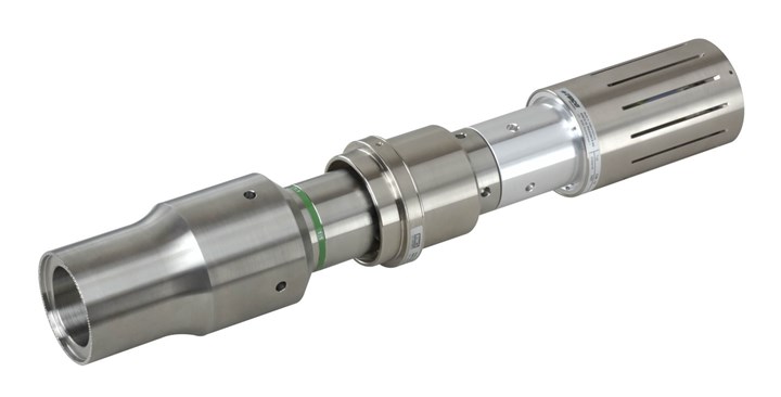
While typically the horn could run for some time with no issues, it may slowly develop high-pitch noises. This may be the time to check the stack assembly, which consists of the converter, booster, and the horn (Fig 4). Removing the stack and each component is the starting point.
Next, look at the mating studs (threaded rod between each component) to see if they are loose or cracked. They can be removed and wiped down with rubbing alcohol and then blown off with clean dry compressed air. Using rubbing alcohol and a nylon brush to clean out the threaded stud hole is also recommended. The mating surfaces can also be blown off with clean dry air. If any of the mating surfaces show any marking or small scratches, a light sanding can be done using 600 grit wet/dry paper. Remember to sand lightly to avoid divots and making the mating surfaces unparallel. In extreme situations, machining the mating surfaces may be necessary.
If the generator is producing a horn fault or a frequency error, check for loose stack components or a broken stud.
Noise issues can also be tied to stack components that are not torqued to the manufacturer’s specifications. A loose stack assembly or an over-tightened assembly can cause noise issues. A sound enclosure would be recommended if the noise originates from the welder and is uncomfortable to the operator. Noise problems are prevalent in larger parts and in applications that have brass inserts being ultrasonically inserted into a plastic housing.
If the generator is producing a horn fault or a frequency error, check for loose stack components or a broken stud. If the horn is in the home position (not touching the part), determine whether an ultrasonic test can be done. If so, press the test button on the generator to see if the horn runs in air. If not, disassemble the stack components and try again. If the generator errs again during the ultrasonic test, try a spare horn and see if the issue resolves itself. If not, the issue could be with the converter or booster.
If the spare horn works, then the original horn should be checked for cracks or damage to the horn face. Cracks sometimes are easy to spot while others can happen internally. If the horn doesn’t run and there are no signs of cracks, then the horn needs to be further tested by a horn analyzer. The horn analyzer can better tell if the horn is cracked. For example, a 20-kHz horn with a reading of 19,750 Hz would be evidence that the horn is cracked. Another way to diagnose a cracked horn is by using a chemical and dye system.
Tackling Excessive Heat
Heat buildup can be caused by a dirty-running horn, the part material, or a poor horn design. Most heat buildup issues come from the speed of the application since the ultrasonic process is based on friction, which causes heat and allows the plastic to melt and then bond. Heat buildup can be reduced by changing to a more forgiving material. A new horn design can also be considered.
Added cooling usually resolves a heat issue. Clean dry compressed air can be blown on the horn face and mating joints of the stack assembly. Typically, just 3-5 psi of compressed air is enough to reduce heat in the horn and stack. Keep in mind that if the heat issue is not addressed over time, it will travel to the converter and eventually cause internal components to fail. A good rule of thumb on air cooling: If the horn is in the home position, the ultrasonics are off (end of weld cycle), and you can’t hold the horn by hand, then it needs to be air cooled. In some extreme conditions, chilled air can be used.
Improper horn rework can also cause many different issues. If a horn has been machined to rework a worn face or a slight modification due to part change, it is very important to have the proper equipment to do a horn scan. Any modifications to a horn can cause issues with uneven amplitude across the horn face, thus increasing or decreasing the horn’s running frequency. These issues could cause failure to other components in the stack and welding system. It is highly recommended to have the manufacturer make the modifications and rework so proper steps are taken to ensure that the horn is running properly and efficiently.
ABOUT THE AUTHOR: Stephen Potpan is on-site manager for Rinco Ultrasonics USA Inc. in Danbury, Conn. He has over 34 years in the ultrasonic welding field, specializing in plastics materials and joint design. Potpan has worked with a large medical company to design test cartridges for rapid microbial identification and detection, which have been tested on the International Space Station. His background also includes stints with multiple manufacturers in the surgical instrument business along with Tier 1 and 2 automotive suppliers. Contact (203) 744-4500; spotpan@rinco-usa.com, rinco-usa.com.
Related Content
What to Look for in High-Speed Automation for Pipette Production
Automation is a must-have for molders of pipettes. Make sure your supplier provides assurances of throughput and output, manpower utilization, floor space consumption and payback period.
Read MoreMedical Molder, Moldmaker Embraces Continuous Improvement
True to the adjective in its name, Dynamic Group has been characterized by constant change, activity and progress over its nearly five decades as a medical molder and moldmaker.
Read MoreFor Extrusion and Injection-Blow Molders, Numerous Upgrades in Machines and Services
Uniloy is revising its machinery lines across the board and strengthening after-sales services in tooling maintenance, spare parts and tech service.
Read MorePHA Compound Molded into “World’s First” Biodegradable Bottle Closures
Beyond Plastic and partners have created a certified biodegradable PHA compound that can be injection molded into 38-mm closures in a sub 6-second cycle from a multicavity hot runner tool.
Read MoreRead Next
Making the Circular Economy a Reality
Driven by brand owner demands and new worldwide legislation, the entire supply chain is working toward the shift to circularity, with some evidence the circular economy has already begun.
Read MoreBeyond Prototypes: 8 Ways the Plastics Industry Is Using 3D Printing
Plastics processors are finding applications for 3D printing around the plant and across the supply chain. Here are 8 examples to look for at NPE2024.
Read More


