Looking into Photovoltaic Film? Here Are Material & Die-Design Insights
The market for high-tech film or sheet used in solar modules represents a considerable opportunity for specialty extrusion processors looking to expand into high-end industries and capitalize on the global shift toward alternative energy.
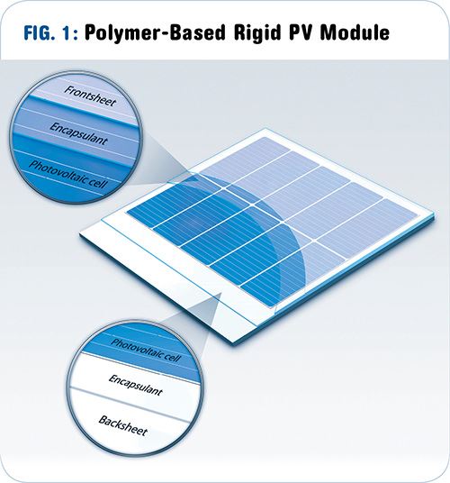
The market for photovoltaic (PV) film or sheet used in solar modules represents a considerable opportunity for specialty extrusion processors looking to expand into high-end industries and capitalize on the global shift toward alternative energy. Solar modules are constructed of solar cells (semi-conductor), contactors, and “packaging” materials (see Fig. 1), which protect the cell. These PV packaging materials are typically processed as polymeric sheets, and the module is fabricated by laminating these sheets to other components.
Getting into this specialty extrusion business requires an understanding of processing highly technical materials. In the case of both the front sheet and encapsulant layers, the materials must be tough enough to survive long-term exposure to heat, damaging UV radiation from the sun, acid rain, large temperature variations, and extreme weather such as snow, ice, and hail.
Cloeren Incorporated has been involved in many projects for PV applications. This article will discuss commonly used materials for this market and—because these materials require specific extrusion technology to be processed efficiently—will offer insights as to what you should be looking for from your die designer.
FRONT SHEETS
Front sheets are the first layer of the PV packaging and are directly exposed to the environment. For rigid modules using crystalline silicon PV cells, the front sheets traditionally have been made of glass. However, there is increasing demand for plastic because of the weight savings and reduced brittleness they provide. In addition, when using fluorinated polymers, performance gains are also feasible with plastic.
Ethylene tetrafluoroethylene copolymer (ETFE), fluorinated ethylene propylene (FEP), and polyvinylidene fluoride (PVDF) are the typical front-sheet candidate materials to replace glass, as they improve light transmission by a few percent. Moreover, fluoropolymers have outstanding weatherability.
ETFE has been used as a glass substitute in architectural applications for many years. The National Aquatics Center in Beijing (built in 2008), the Allianz Arena in Munich (2004), and the Eden Project in the U.K. (2001) are among the most famous buildings using ETFE sheets in place of glass. This material was chosen primarily for its transparency, weatherability, weldability, and light weight, allowing for interesting design options.
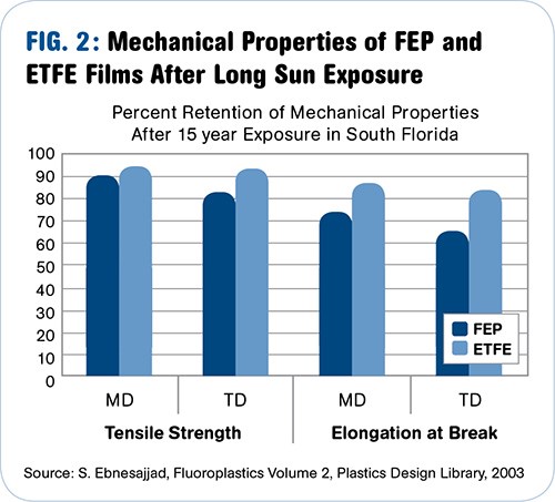
Naturally, over the years these buildings have been exposed to various weather conditions and pollution from the atmosphere. Historical data from the resin suppliers suggests a small loss of mechanical and optical properties over time for both FEP and ETFE (Fig. 2). For these types of advanced applications, accelerated weatherability tests are performed to validate the material selection and the construction of solar modules.
Fluoropolymer front sheets are typically manufactured by cast film extrusion. The process, however, poses some challenges that processors need to consider when specifying the die. First off, fluoropolymers are very corrosive—hydrofluoric acid (HF) gas can be released in the event of thermal degradation of the material. So the metal surfaces in contact with the melt should ideally be made of high-nickel-content alloys with small amounts of iron (so-called superalloys), which have excellent corrosion resistance. A technical challenge posed by these alloys, however, is that because of their low yield strength (in the range of 300 MPa at extrusion temperatures), permanent deformation of the die flex lip is a potential problem. For this reason, ensure that age-hardenable superalloys are used by your die maker, as they combine outstanding corrosion resistance and improved mechanical properties over the standard superalloys.
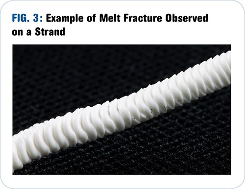
Another challenge when extruding fluoropolymer films is their tendency to develop melt fracture at relatively low shear stress values, referred to as critical shear stress. Melt fracture is a form of flow instability that initiates in the flow channel and further develops downstream of the die lips in the air gap. It affects the film surface quality and thus the optical properties of the film.
An example of melt fracture observed on a strand obtained from a capillary rheometer is shown in Fig. 3. The low value of critical shear stress can be a limitation on the achievable film thinness (fluoropolymer front sheets are typically about 50 microns thick) or extrusion throughputs.
Consequently, when specifying a die, make sure your designer knows the limitations of the material, which can be determined by extensive rheological characterization. Melt fracture is not unique in fluoropolymer processing; extruders of polyolefins and other materials are familiar with the phenomena. While processing aids are typically used to thwart melt fracture in polyolefins, there are few commercial processing aids for fluoropolymers.
Each fluoropolymer family has a different critical shear-stress value. There are also differences within the same family, depending on molecular-weight distribution and the nature and content of comonomers.
The flow distribution provided by the die flow-channel design must be optimized across the die width. Obtaining a gauge as close as possible to the target is not only critical for the performance of the film, but can also generate substantial cost savings, especially because the materials can cost 20 to 30 times more than typical polyolefins. To that end, make sure your die has an automatic profile control system.
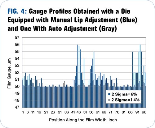
To demonstrate the importance of automatic gauge control, imagine the following scenario: A line producing 100-in.-wide fluoropolymer film with a minimum thickness requirement of 0.002 in. (50 microns) at a line speed of 50 ft/min uses manual lip adjustment. A hypothetical gauge profile is shown in blue in Fig. 4 and exhibits a deviation at 2σ of 6.0% (where σ is the standard deviation) and an average thickness of 51.19 microns. The fluoropolymer resin density is nominally 2 g/cm3 and its cost is assumed to be $15/lb in this example.
Alternatively, imagine the case where the same line is equipped with an auto-die-control system, which achieves the gauge profile shown in gray in Fig. 4. This gauge profile represents a deviation at 2 σ of 1.4% and the average gauge is 50.29 microns.
In this hypothetical scenario, on a line running for 1000 hr, the material cost savings are about $165,000 when using the automatic profile control system feature instead of manual lip adjustment. This calculation only captures the materials savings during steady-state extrusion. Additional material cost savings could be possible, as auto die control also lets you get up to specification quicker.
Having a perfectly balanced flow channel is also extremely critical: Reducing lip adjustments will minimize potential local high-shear regions, which could trigger melt fracture.
Finally, fluoropolymers are processed at high temperature and can be somewhat heat sensitive because the degradation temperature is usually close to their processing temperature. As explained earlier, thermal degradation of fluoropolymers can have significant consequences. Good thermal control is therefore required throughout the process.
For dies, make sure your supplier optimizes the location of heaters and thermocouples to provide uniform temperature to the polymer flowing through the die. Additionally, location of thermocouples near the manifold channel captures information coming from the melt temperature and will be able to give clues about extrusion conditions and incoming melt quality.
THE ENCAPSULANT
Encapsulants for PV modules also have many requirements depending on the technology of the PV cell used in the module. Encapsulants can be seen as the glue between the front or back sheet and the PV cell. Therefore, they need to provide excellent adhesion between these components, which is achieved via lamination. They also have to be transparent and provide outstanding electrical insulation and impact resistance to the module. All these properties must be retained after years of exposure to the UV from the sun or other severe weather conditions.
The typical material, by far, used for encapsulant sheets is ethylene vinyl acetate copolymer (EVA). It is a well-known polymer with about 30 years of data, and the lamination process is also well established. The final properties are obtained by crosslinking the EVA with organic peroxide initiators. Other materials of choice for this application include polyvinyl butyral , ionomers, thermoplastic urethane (TPU), and polydimethylsiloxane (silicone rubber).
EVA encapsulants are produced in sheet form, and the extrusion process can use either one or two steps. In the two-step approach, the crosslinking agent can be compounded into a polymer masterbatch. This masterbatch is then blended with the EVA and run in a single-screw extruder with a flat die. An alternative method would be to compound the crosslinker with the EVA polymer in-line with sheet extrusion. This latter process would typically use a co-rotating twin-screw extruder, a gear pump, and a sheet die.
There are some challenges associated with the processing of EVA. First, since the compound is potentially reactive, it is critical not to initiate premature crosslinking in the extrusion system. In the extruder, good dispersion must be achieved without overheating the material. In the die, the melt temperature and residence time must be kept under control.
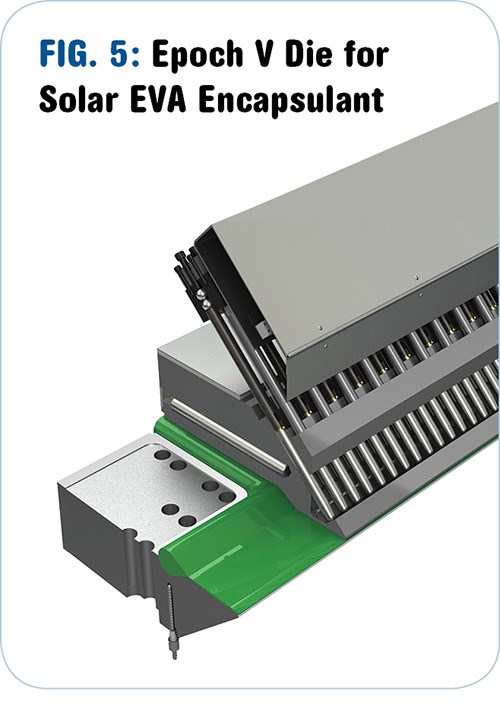
Good temperature control of the die is achieved by optimized location of the thermocouples and the body heaters. A cutaway view of a typical EVA extrusion die is shown in Fig. 5. Control of melt temperature, however, depends greatly on viscous dissipation, because of the relatively high viscosity of solar-grade EVAs at the low extrusion temperature of about 210 F (100 C). For this reason, keeping the melt from overheating in the die by shear and/or pressure is addressed predominately through flow-channel design.
As the kinetics of crosslinking reactions are temperature and time dependent, low residence time in the die is also desirable. The flow-channel design is therefore a non-trivial balancing act between low residence time and low shear stress (or pressure drop). These are contradictory requirements, as low residence time typically requires smaller flow-channel volumes, and low shear stress usually results from larger flow-channel volumes. Die-design experience and advanced design tools such as 3D flow simulation can be used to approach the optimal design solution
Related Content
How to Decrease the Extrudate Temperature in Single-Screw Extruders
In many cases, decreasing the discharge temperature will improve product quality and perhaps even boost rate. Here are ways to do it.
Read MoreExtrusion Excellence: This Year's Top Stories
Revisit the year’s most popular articles on extrusion technology and processes, showcasing innovations, best practices, and the trends that captured the plastics processing community’s attention.
Read MoreMaking Gains in the Drain Game
AWD blends extrusion and thermoforming technologies with plenty of home-brewed equipment and processes to keep water away from where it isn’t supposed to be.
Read MorePTi Makes Changes in Leadership Structure
Moves aimed at bolstering the future of the sheet extrusion manufacturer.
Read MoreRead Next
Shining Opportunities In Solar Films
Photovoltaic markets are growing explosively, and so are opportunities for specialty film producers. Solar cell and module production, which was forecasted to grow at 50% a year for the next few years before the recession hit, is now expecting slightly more healthy 30% annual growth, according to DuPont, a major supplier of photovoltaic film materials. Solar cell and module manufacturers are expanding, and large numbers of new companies are entering the field.
Read MoreBeyond Prototypes: 8 Ways the Plastics Industry Is Using 3D Printing
Plastics processors are finding applications for 3D printing around the plant and across the supply chain. Here are 8 examples to look for at NPE2024.
Read More
