Maximize the Cooling Capacity of Your Extrusion Line
Maximizing output in extrusion requires a thorough understanding of not only the cooling requirements of the extruder but of the extrudate as well.
Throughout my career, I have been frequently involved in projects focused on improving the output and consistency of extruders. Yet, interestingly, there have been relatively few inquiries over this time about how to optimize the cooling of the parts being extruded.
Recently, though, I have gotten some inquiries about ways to increase overall extrusion line output where the limits turned out to be more related to cooling after extrusion than the extruder itself. This seems to be more typical where the processor cobbles lines together from various sources, or tries to upgrade the extrusion capacity without in-depth knowledge of the available cooling capacity.
The cooling capacity must be matched closely to the extrusion capacity to benefit from any improved extrusion techniques and equipment. Most extruded products are cooled by some type of polymer-to-water heat transfer method. Simple water immersion is typically used for products like pipe, tubing, cable, strand, filament and most profiles, while sheet is cooled on chill rolls with internal water flow.
Know the Heat Load
In every case, to get the results you want, you must have a complete knowledge of the “heat load” before you can determine if enough cooling capacity is available. An approximate heat load is relatively easy to determine: multiply the specific heat of the particular polymer by the desired output and the required temperature change to properly handle the extrudate after cooling. That will give you an accurate enough estimate of the total heat load for evaluating all the components of the cooling system.
There are some lesser factors to be considered if extreme accuracy is required. Because all polymers have different specific heats and different line exit temperatures to reach proper handling temperature, almost every extrusion operation is a different case.
Cooling capacity must be matched closely to the extrusion capacity to benefit from any improved extrusion techniques and equipment.
For example, with this simple calculation I estimated that a cooling system that could adequately cool 2,000 lbs/hr of HIPS would only be able to cool about 650-750 lbs/hr of HDPE. I recently worked with a processor who compared different polymer line rates just based on output. He was quite disappointed. Again, that’s because he did not take into account the broad differences in polymer thermal and physical properties. So it's necessary to make the heat load comparison in all cases, because even different processes with the same polymer may have different heat loads due to differing melt temperature or required handling temperature.
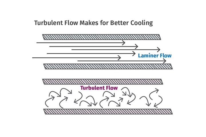
FIG 1 Water (or air) cooling is much more effective with turbulent flow than laminar flow. In laminar flow, a thin boundary layer of the fluid tends to stay stationary on the surface of the extrudate, serving to insulate the extrudate from the main coolant flow. Turbulence breaks that layer up to expose the extrudate to the main coolant temperature. Source: J. Frankland
Typically, a water chiller is used to remove the polymer heat from the process water and return cool water at the necessary temperature to continue the process. That’s the first point of the investigation. Is the chiller large enough to handle the heat load with a little reserve? Chiller capacity is usually expressed in “refrigeration tons,” with one ton equaling 12,000 BTU/hr. The flow rate of the cooled water must also be known and that may be from an integral pump system for the chiller or a separate stand-alone pumping system.
If pumping is part of the chiller system, that information is usually available from the manufacturer of the chiller. If a separate pumping system is used, its pumping or flow rate through the process is equally important at various pressures.
The remainder of the system performance is not so easily determined. The pressure drop through the whole coolant piping system from the reservoir and back must be determined to see what the actual flow rate will be as pump capacity is pressure sensitive.
Understanding Turbulent Flow
Water (or air) cooling is much more effective with turbulent flow than laminar flow, whether it is in an open tank, a chill roll or a mold. That’s because a thin boundary layer of the fluid tends to stay stationary on the surface of the extrudate, serving to insulate it from the main coolant flow. Turbulence breaks that layer up to expose the extrudate to the main coolant temperature. In an article I wrote in 2017, I discussed the effect of turbulence and its effect on improved cooling. The Reynolds number quantifies the flow rate in terms of laminar versus turbulence.
Turbulent flow increases convective heat transfer, increases mass transfer and mixing, and reduces drag — all of which are favorable to increased cooling of the extrudate.
Reynolds numbers (Re) below 1,000 are considered indicative of laminar flow. Numbers ranging from 1,000 to 10,000 are considered a transition zone, and beyond that is turbulent flow. Turbulence is determined by calculating the Reynold’s number as follows:
Re= udn/V, where
u = velocity, dn = hydraulic diameter, and V = kinematic viscosity.
For example, a change in flow rate resulting in a change in Reynolds number from Re = 1,000 to Re = 3,000 results in an increase of more than two times the convective heat transfer. It would require a significant change in water temperature to match the effect of turbulence.
How do you apply this to your process? Each process has to be treated a little differently, but with the same goal — to achieve turbulence at the heat-exchange surface to maximize heat transfer. For example, in a chill roll for sheet/cast film, cooling turbulence is created in the spiral wraps to cool the shell. In profile tooling, turbulence is established in calibration tooling and subsequent coolant tanks.
Turbulent flow increases convective heat transfer, increases mass transfer and mixing, and reduces drag.
In processes where the tooling does the cooling, the Re can be used to size the cooling channels and even the velocity in the surface film in the calibration tooling. However, in large cooling tanks it’s more difficult to establish turbulent flow. So for pelletizing, pipe, tubing and some profile applications, it may be hard to significantly increase the velocity of the cooling water to the turbulent range. In those cases, you can use jets, bubblers or baffles to generate the localized velocity necessary to break up the boundary layer.
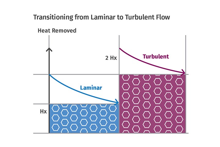
FIG 2 In the transition from laminar to turbulent flow, the (hx) or heat flow from a heated surface essentially doubles. This occurs with a very small increase in coolant flow rate, so it’s critical in every cooling system to know the exact flow and resulting Reynolds number.
Even though the temperature of the overall mass of water may remain low, the invisible boundary layer and its temperature gradient surrounding the extrudate restrict heat transfer.
In the transition from laminar to turbulent flow, the (hx) or heat flow from a cooled surface essentially doubles. This occurs with a very small increase in coolant flow rate, so its critical in every cooling system to know the exact flow and resulting Reynolds number. Again, a transition in smooth pipes typically occurs at a Reynolds number of 2,300-3,500, while in an open bath turbulence can occur between 500-2,000.
In summary, the cooling capacity calculations are a little different than extruder output calculations and can be complicated to determine as there are often a long series of components in the cooling system for evaluation. Then that must be compared to the heat load. However, the potential extrusion capacity can never be fully utilized if it’s not matched by the cooling capacity.
ABOUT THE AUTHOR: Jim Frankland is a mechanical engineer who has been involved in all types of extrusion processing for more than 45 years. He is now president of Frankland Plastics Consulting LLC. Contact jim.frankland@comcast.net or 724-651-9196.
Related Content
The Effects of Time on Polymers
Last month we briefly discussed the influence of temperature on the mechanical properties of polymers and reviewed some of the structural considerations that govern these effects.
Read MoreThe Effects of Stress on Polymers
Previously we have discussed the effects of temperature and time on the long-term behavior of polymers. Now let's take a look at stress.
Read MoreWhy Shoulder Bolts Are Too Important to Ignore (Part 1)
These humble but essential fasteners used in injection molds are known by various names and used for a number of purposes.
Read MoreBack to Basics on Mold Venting (Part 1)
Here’s what you need to know to improve the quality of your parts and to protect your molds.
Read MoreRead Next
Lead the Conversation, Change the Conversation
Coverage of single-use plastics can be both misleading and demoralizing. Here are 10 tips for changing the perception of the plastics industry at your company and in your community.
Read MoreFor PLASTICS' CEO Seaholm, NPE to Shine Light on Sustainability Successes
With advocacy, communication and sustainability as three main pillars, Seaholm leads a trade association to NPE that ‘is more active today than we have ever been.’
Read More
.jpg;width=70;height=70;mode=crop)


