Put the Oomph Back in Your Vacuum System
Thiele on Conveying
You can make these enhancements to your resin conveying with a better understanding of three critical elements: Air, vacuum receivers, and piping.
Increase capacity…convey longer distances…improve performance... and eliminate plugged lines, abrasion, and angel hair. You can make these enhancements to your resin conveying with a better understanding of three critical elements: Air, vacuum receivers, and piping. They are the keys to optimizing the performance of your vacuum system.
THE IMPORTANCE OF AIR
A system with too much air creates problems that manifest in excessive pressure drop, wear and tear on equipment, and product degradation. But a system with too little air won’t convey anything. The air moving through the pipe must have a velocity sufficient to pick up, accelerate, and carry the material to the destination. Pick-up velocities range from about 3000 to 4000 ft/min for most plastics.
The minimum velocity will vary based on material bulk density, particle size, and configuration of the plastic. For example, polyethylene at 35 lb/ft³ requires a pick-up velocity of about 3000 ft/min, while PET at 55 lb/ft³ requires about 3500 ft/ min.
Vacuum pumps and blowers generate the air volume required to create the velocity and overcome the resistance that is created as the material moves through the pipe, elbows, vacuum receivers, and filters. This resistance is expressed as inches Hg vacuum. When the resistance exceeds the vacuum that is available at the pump, either the vacuum relief valve will activate or the blower motor will overheat. In either case, you have a problem.
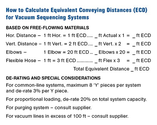
Material characteristics, capacity, and conveying distance are all taken into consideration when sizing a system. The energy required to move the material through the pipe depends on the horizontal distance, vertical lift, elbows, and flexible hose. All these factors are taken into consideration to arrive at an Equivalent Conveying Distance (ECD). The chart on p. 30 shows how the ECD is calculated. Once it is established, it is coupled with performance curves to assist in the selection of the appropriate line size and vacuum pump for the specific application.
The capacity of a vacuum system with a given line diameter can vary, and there are four types of pumps commonly used. Each can bring a different result in maximum conveying distance and capacity achievable through a given pipe diameter.
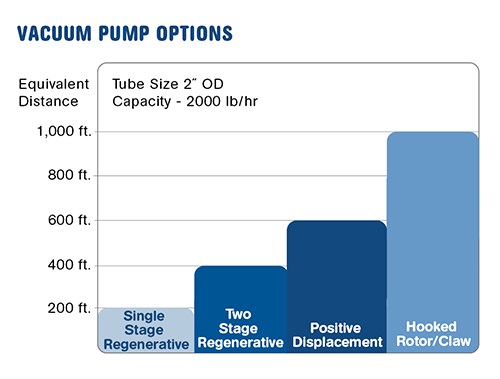
•Single-stage regenerative or side-channel blowers operate at up to 8 in. Hg and work well for short distances and light conveying loads.
•Two-stage regenerative blowers operate at up to 10-12 in. Hg and operate well at mid-range distances and capacities.
•Positive-displacement blowers can operate at up to 14-16 in. Hg, although most are sized for 12 in. These are well suited for longer distances.
•Hooked-rotor or “claw”-type vacuum pumps operate at up to 22 in. Hg and are suited for higher rates and conveying distances up to 1000 ft of ECD and beyond.
The effect of changing pumps on an existing system can be seen in Fig. 3. Shown are the pump options for a system with tube diameter of 2 in. and a conveying rate of 2000 lb/hr. The bars indicate the conveying distance that can be achieved with the various pump types. There are no changes in line size or velocity for any of these pumps. What is changed in each case is the amount of resistance that the pump senses due to the increased conveying distance.
Another method to increase the capacity of an existing system is to change the sheaves on the pump and increase the speed. This will often work, but be careful: When you increase the speed you increase both the air flow and velocity, and this action will affect the energy consumption. You will want to review a blower performance curve or consult an industry specialist before taking this path.
So, if your system is not keeping up, you need to increase the conveying distance or increase your conveying capacity. You have a couple of options: You can change the sheaves and increase the pump speed or move up to a pump with greater vacuum capability.
THE VACUUM RECEIVER
After air, the vacuum receiver is the item that probably has the greatest impact on system operation and efficiency. The primary objective of a vacuum receiver is to separate the incoming material from the conveying air stream. Most vacuum receivers use a filter or screen to separate the air from the material. Angel hair, dust, and fines collect on the filter, and as the filter begins to plug, the pressure drop increases. The increase in the pressure drop across the receiver means that there is less vacuum available to move material, with the end result being a plugged line, a vacuum relief going off, a motor burnout, or a starving machine. Nothing good!
A low, consistent pressure drop across the receiver is critical for efficient conveying.
Simplified manual removal and cleaning systems for the screens have been available for some time. But the receiver is often in a location that is difficult to access and by the time you get to it, it is too late. The plugged filter has caused a shutdown. Additionally you have the issue of dust control once you remove the screen and shake off the dust.
A better solution is a compressed-air “blowback” system. These systems pulse compressed air to the filter after each fill cycle and can add as much as $1000 to the cost of a single receiver. Be sure the compressed air is dry and the system is tight, as the compressed-air pulses may send dust into the plant atmosphere.
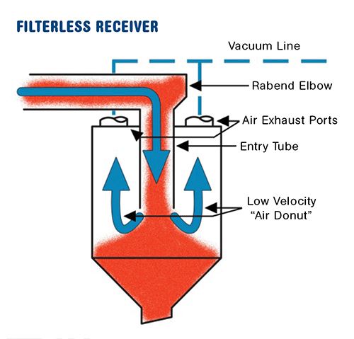
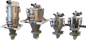
A third option is to just eliminate the receiver’s filter or screen altogether. Figure 1 shows a patent-pending design where the material is fed through the top of the receiver and flows through an infeed tube into the center of the vessel. As the material exits the tube it settles, and the conveying air escapes around the tube in an air channel, or “donut.” The upward velocity in the “donut” ranges between 250 and 300 ft/min. This is less than 10% of the pick-up velocity required to convey, and hence the material cannot be picked up and carried to the exhaust ports and vacuum line. Now you have eliminated the plugged filter, high pressure drop, blowback, and dust problems. Most existing receivers can be retrofitted to accommodate this design.
THE PIPING SYSTEM
An often overlooked potential problem area that can affect conveying efficiency and capacity is the vacuum line, a pipe that carries the air from the vacuum receiver to the vacuum pump. A vacuum line of 100 ft in a 2-in. system will consume about 1 in. Hg. If the distance is 300 ft, the system will consume about 3 in. Hg. Since you are just moving air through this line, it is possible to increase the vacuum line diameter to 3 in. and not affect the material conveying.
This will reduce the pressure drop by almost 50%, leaving an additional 1.5 in. Hg available for material conveying. Reducing the pressure drop in the vacuum line can increase the capacity of your system.
So if you are close to reaching your capacity requirements and have a very long vacuum line, you may not require a new pump—just a larger vacuum line.
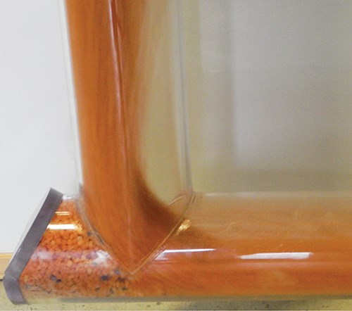
Soft or abrasive materials present another set of issues. In the case of soft PE or polyurethane, you may get angel hair; while glass-filled materials will just blow holes in the pipe. First thing to do is check on the conveying velocity and be sure it is not excessive. Both of these problems will first appear in the elbows. In traditional long-radius elbows, the material impacts against the elbow wall, causing the angel hair or abrasive wear. Figure 2 shows a cutaway of a right-angle-bend elbow with a pocket where the material impacts on itself, eliminating both the friction that causes the angel hair and the impact points that cause abrasive wear.
In the tradition of talk-show host David Letterman, here are the “Top 10” things you need to know to maximize your vacuum-conveying efficiency:
•Consistent, non-varying pressure drop pays big dividends.
•Eliminate long, small-diameter vacuum lines.
•Adjust blower speed to get the velocity right.
•Provide uniform, non-slugging feed of material into the air stream.
•A vacuum switch and alarm can alert you to plugged filter problems at the blower before they become critical.
•Long-radius elbows are not always the answer.
•Try a purge valve if you have over 25 ft of vertical lift and are plagued with line plugs.
•Simultaneous loading, where two receivers can be filled at the same time with one pump, is an option that will pay for itself.
•Check for leaks in flex hose, elbows, and impact points.
•Know the velocity calculation:
cfm ÷ pipe area ft² = velocity.
Related Content
Safety, Recycling, and Compounding Trends Bring New Opportunity to 70-Year-Old Company
NPE2024: Vac-U-Max presents pneumatic conveying solutions for powdered materials.
Read MoreConair Names New Head of Customer Care
Jared Helfrich to direct the efforts of the machine builder’s growing customer care group, combining its existing parts and service and repair organization with a new range of fast-growing customer services.
Read MoreSingle View of Bin & Silo Material Levels in Multiple Locations
Got a bin in Buffalo and a silo in San José? BinMaster’s latest addition to its cloud inventory software lets you see all your resin inventory anywhere in one view.
Read MoreCentral Controller, Energy-Efficient Pump for Conveying
Wittmann debuts new control system and pump at Fakuma.
Read MoreRead Next
Making the Circular Economy a Reality
Driven by brand owner demands and new worldwide legislation, the entire supply chain is working toward the shift to circularity, with some evidence the circular economy has already begun.
Read MoreFor PLASTICS' CEO Seaholm, NPE to Shine Light on Sustainability Successes
With advocacy, communication and sustainability as three main pillars, Seaholm leads a trade association to NPE that ‘is more active today than we have ever been.’
Read More
