You can draw a parallel between diagnosis of twin-screw compounding extruders and of the human anatomy. When you go to a physician to diagnose your ailment, the first question is designed to lead the investigation in one of two directions: “How long have you had this problem?” If you respond that the problem started when you were a child, this will lead the doctors down the “disease” pathway, eliminating the possibility that this is a temporary situation. If you reply that the problem started yesterday, this will limit the investigation to your activities within the past 48 hr only.
Chronic compounding problems are like diseases—they are always present, and the cure requires extensive treatment, while transient problems can be thought of as “illnesses.” An illness is temporary, and the treatment is relatively simple (e.g., take some medication and rest for 24 hr).
We identify problems in compounding as “chronic” if the results are the same every time a particular formulation is run—every lot produces the same results: poor physical properties, black specks, strands dropping, die holes freezing, vent ports fouling, etc. In these cases, the problem cannot be the result of a particular lot of raw materials, worn extruder components or any other temporary condition. The symptoms of chronic problems suggest that the process itself is the problem: improper screw/die design and/or operating conditions. For these problems, the treatment requires redesigning the screw configuration or modifying the compounding process. This is the only way to cure such problems.
We identify problems in compounding as “chronic” if the results are the same every time a particular formulation is run.
On the other hand, if a particular compound has been produced successfully in the past, and today it runs differently—this is the symptom of a temporary illness. Now we must determine why the current condition exists and whether it is causing compound quality problems or processing problems. Illnesses are most commonly associated with specific lots of raw materials, mechanical failures (burned-out heater, leaky solenoid valve, etc.), environmental conditions, operator error or machine wear—all of which appear over different time periods.
Look for Patterns
Most modern compounding lines continuously log all the process data, which can be graphically displayed as trend curves over some defined time interval. When viewed in this way, it becomes obvious that there is a pattern to the variation … or not. These patterns are not readily seen when viewing numerical information on the extruder control screens. The most common temporal (time-based) and spatial (relative to one specific area) patterns observed during compounding operations are described below with typical root causes.
Shift: We describe this first pattern as a “shift”—when the measured parameter moves up or down to a new equilibrium position and remains stable at the new level (Fig. 1). Measured parameters can be any process variable (percentage torque, die pressure, melt temperature, etc.) or any product quality attribute (melt flow index, percentage ash, color, tensile property, etc.). We should also consider the time frame over which the shift occurred—e.g., gradual change over hours or rapid change within a few minutes—to assist in identifying possible causes.
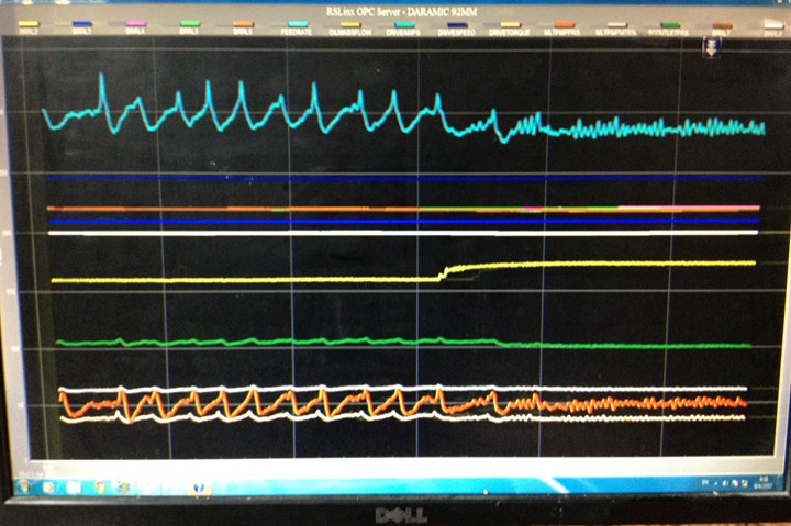
FIG 1 In a “shift,” the process changes to a new equilibrium position and remains stable thereafter. (All images: CPM Extrusion Group)
Which parameters can change like this? Over what time scale? Raw-material lot changes can appear like this, changing the rheology in the extruder as soon as the new lot enters the machine. The process (and product) moves quickly to a new and stable condition. The affected parameters can include motor load (percentage torque), discharge melt temperature and pressure, product melt-flow rate.
Changes in environmental conditions (ambient temperature and/or relative humidity) can influence raw-material temperature, for example, if the resin feedstock is stored in outside silos. Significant changes in ambient temperature can occur within 12 to 24 hr, for example, but generally not in less time than this. As a result, the process will shift gradually over this time frame until reaching a new equilibrium.
Trend: Nearly every aspect of twin-screw compounding exhibits some degree of short-term variation—e.g., barrel temperatures, motor load, die pressure, feeding rate. However, the average value remains constant. In the case of a trend pattern, the average value is increasing or decreasing continuously over some longer time frame (Fig. 2).
We can rule out some variables: For example, raw-material lots do not change in one direction only. Common variables that do tend to trend include barrel temperature caused by cooling-valve failure; pellet size and shape caused by die-hole freeze-off (e.g., caused by a burned-out heater); product porosity caused by vacuum-system fouling (accumulation of material over time in vacuum piping).
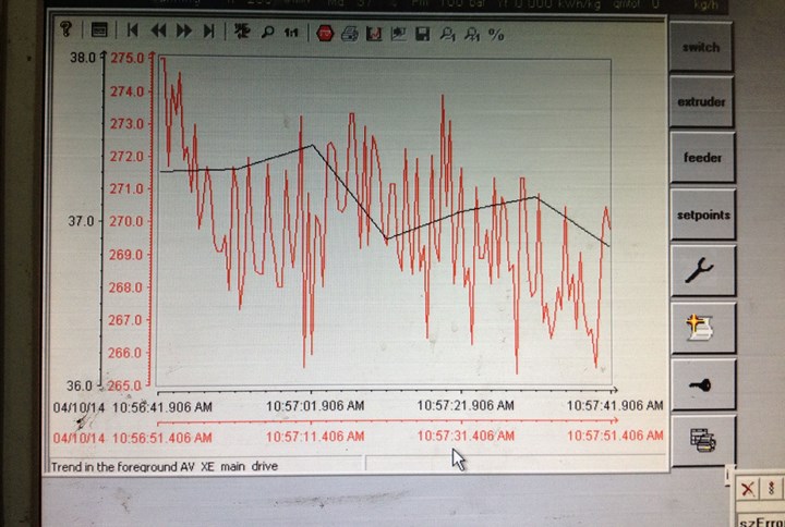
FIG 2 While there are clear signs of variability in a trend, the overall value of the parameter is moving up or down over a larger time scale, similar to the stock market’s short-term fluctuation underlying longer-term growth.
The source of change (e.g., failed component like a cooling solenoid valve) must remain in the failed state throughout the remainder of the production lot for the trend pattern to continue.
Nearly every aspect of twin-screw compounding exhibits some degree of short-term variation.
As opposed to looking for a trend from a single production lot, we could look at many different lots in sequence to see the trend from screw or barrel wear, as this time scale is months or years.
Oscillation: What is an acceptable amount of variation, for example, for barrel temperature? How much variation in percentage torque or melt pressure is normal?
Regular variation is to be expected for most of the process parameters and product properties, as there is inherent “noise” in most measurements and also variation associated with PID control loops (Fig. 3). Some acceptable tolerances:
• Temperature control: ±5° C (10° F).
• Motor load/amperage/torque: ±2-3%.
• Feeding rate: ±1-2%.
• Ash content: ±1-2% (should be same as feeding rate).
• Melt pressure: ±2-3%.
For variation greater than “normal,” search for the underlying causes. In the case of feeder variation, for example, if the speed of rotation of the metering screw is too slow, that results in surges of material being discharged from the feeder. These surges then induce variation in motor load and melt pressure in the extruder. In the case of barrel-temperature control, we must look at PID parameter tuning and adjustment of cooling valves (e.g., barrel cooling-water flow-control valve settings), When these manually adjusted cooling valves allow too much water flow, this results in large fluctuation in barrel temperature.
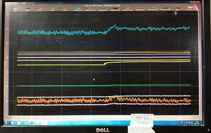
FIG 3 During oscillation, the process parameter or product-quality attribute (e.g., percentage ash) is moving up and down at some regular frequency. How much variation is normal? What is the frequency? What is the root cause of the variation?
The frequency of fluctuation will depend on the source of variation (e.g., pulsation associated with screw feeders; opening of barrel-cooling solenoid valves) but is typically within seconds or minutes. When looking at longer time scales, we could also see the variation in environmental temperature or humidity from day/night—or even seasonal changes—having some influence in the compounding operation.
Many plant managers see the effect of shift change (e.g., regular variation every 8 to 12 hr), suggesting that the extruder operator influences the process measurements or product quality.
Upset: Upset conditions are extremely hard to diagnose since the parameter always returns to the initial equilibrium condition following the upset (Fig. 4). There is no pattern or regularity for the time between upset conditions or the amount of deviation during the upset condition. Such isolated incidents could be triggered by external influences, like incoming power surges, which must be included in the investigation.
Most common upset conditions are related to accumulation of raw material (e.g., powder buildup in feed hoppers) that eventually avalanches into the extruder, causing torque spikes. There is no regularity to the frequency of occurrence, and may be related, for example, to environmental conditions. Consider the case where the accumulation of powder only occurs when a specific filler type is run and when there is also high relative humidity.
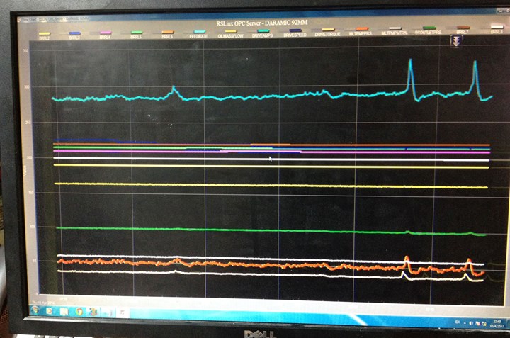
FIG 4 Upset conditions are extremely hard to diagnose since the parameter always returns to the initial equilibrium condition after the upset. There is no pattern or regularity for the time between upset conditions or the amount of deviation during the upset condition.
Identifying the root cause for upset conditions often requires review of multiple lots over a much longer time scale (e.g., months apart) to determine if environmental conditions or machine wear has any influence.
Most common ‘upset’ conditions are related to accumulation of raw material that eventually avalanches into the extruder causing torque spikes.
Spatial patterns: When a product quality problem appears at a specific location or position (e.g., only on the outer portions of the die), we can isolate the possible causes by considering how the extruder interacts with the die forming operation (Fig. 5).
For twin-screw compounding extruders, the melt leaving the screw tips is fairly well mixed prior to arriving at the die entrance. To illustrate this, if you drop one black-colored pellet into a light-colored polymer through the vent port that is typically located at the very end of the extruder, the black color will be well dispersed across the entire die opening. The screws that are usually installed after the vent port are only conveying screws without any mixing elements—yet the color is well mixed throughout. What this implies is that any defect in the material exiting the screws will be very well distributed across the entire die; unmixed filler or unmelted polymer will not prefer to flow to one part of the die versus another.
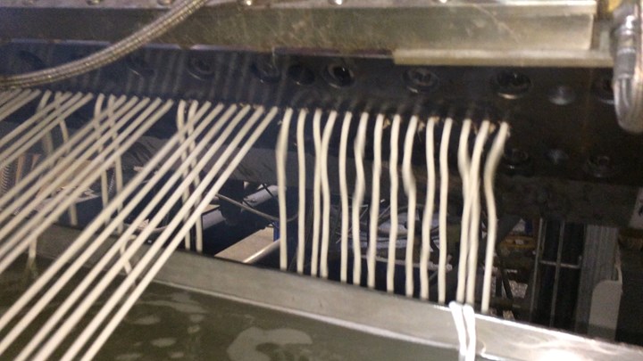
FIG 5 Spatial patterns are associated with product-quality defects as well as processing variables. Why does the product flow differently throughout the die plate? Why is the product hotter in the center of the die?
Understanding that there is no mixing after the screw tips, any problems that appear within a specific area of the die cannot be caused by the extruder: poor flow from specific die holes, darker strands or black specks that appear only on certain strands (Fig. 6). In these cases, the problems are created after the screw tips in the adapter, screen changer or die body.
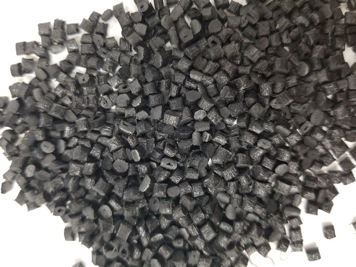
FIG 6 Are voids in the pellets of different sizes and randomly distributed (suggesting a problem with degassing in the extruder), or are they all the same size and always located in the center of the pellet (“shrink voids” usually associated with insufficient cooling downstream of the extruder)?
Bottom line: teach your staff to look at trend curves (a “history” feature is available on most extruder control screens that provides graphs to track specific parameters over time) for patterns that can quickly lead to or eliminate specific root cause(s).
Along with staff training, a good preventive-maintenance program is also required to eliminate some of the “usual suspects” from causing most problems related to mechanical failures.
ABOUT THE AUTHOR: Adam Dreiblatt has more than 35 years’ experience with twin-screw extrusion as a consultant, teacher and practitioner. He is currently dir. of process technology for CPM Century Extrusion, which supplies compounding extruders and replacement parts. He provides technical support to the sales organization and customer base, as well as technical support for sister company Ruiya Extrusion in Nanjing, China. Contact: 231-421-6896; dreiblatta@cpm.net; centuryextrusion.com.
Related Content
Engineering Resins Compounder Expands to Take on More Scrap
Polymer Resources responds to sustainability push by upgrading plant with grinding and shredding equipment to take on both postindustrial and postconsumer reclaim.
Read MoreHow to Maintain Pelletizing Quality When Acid Attacks
Developments in the chemistry of polymers and additives have made corrosion a real problem in pelletizers. Here’s how to ward it off.
Read MoreSirmax Adapts Integrated Recycling Approach to US Supply Conditions
Integrating compounding and recycling to leverage untapped postindustrial recycling feedstocks.
Read MoreHow to Configure Your Twin-Screw Extruder: Part 3
The melting mechanism in a twin-screw extruder is quite different from that of a single screw. Design of the melting section affects how the material is melted, as well as melt temperature and quality.
Read MoreRead Next
In Twin-Screw Compounding, Distinguish Between ‘Disease’ and ‘Illness’
The concept of troubleshooting in compounding can be defined in terms of a problem (or problems) with compound quality or as a problem with the compounding process.
Read MoreTroubleshooting the ‘Mixing Experience’ in Corotating, Intermeshing Twin-Screw Extruders
The metering equipment, twin-screw extruder and downstream systems all must work in concert to control the properties of the final part and manage the process of mixing.
Read MoreUse These Twin-Screw ‘Tools’ to Improve Quality of Your Color Pigment Dispersions
A twin-screw compounding extruder is a single piece of equipment divided into distinct unit operations. Thinking of each unit operation as part of a toolbox can help determine what can be added or improved to process best-quality color masterbatches.
Read More

