Here is the classic frustration for the engineer inventor: A big, breakthrough idea that ought to be attainable advances through 90% of the development needed to make it real, only to stall at that point because of one vexing, unanticipated detail that presents a problem too difficult to solve in a cost-effective way. For ReelView Fishing and its system for underwater real-time fishing video, that problem was a cable connector.

The ReelView Fishing system offers a way to obtain real-time underwater video of fishing on the angler's smartphone. Source: ReelView

The fishing line serves as the signal transmission cable. For the inventors, the challenging component of this system was the connector merging this line to the camera. Source: ReelView
Solving the problem of this connector (and it has, thankfully, now been solved) ultimately required the startup company to invent not just its new technology for fishing, but also an entirely new underwater connector design. Realizing this design — getting to the answer quickly and then being able to manufacture it — presented molding and moldmaking challenges that 3D printing answered in two different ways. In the solution ReelView found, developed with the aid of injection molding specialist Alba Enterprises, LLC, 3D printed steel mold tooling is used for overmolding around a 3D printed polymer component of the connector.
The resulting success provides an example of what may well be the most transformative role additive manufacturing is set to play in moldmaking, particularly as it relates to AM making steel mold tooling. Attention to AM in moldmaking sometimes focuses on AM-enabled internal features such as conformal cooling channels. However, the advance of metal additive for moldmaking has also improved the speed with which AM can deliver a tool. This speed improvement has significant implications for product development, and the leaders of both companies experienced this with the connector application.
“Iteration is the area where additive helped us so much,” says ReelView founder Dustin Alinger. The molds used to make successive versions of the connector design could have been made conventionally through machining instead of 3D printing (there are no conformal cooling lines, for example), but he says the molds could not have been delivered as cheaply or as quickly in this way. For each new connector redesign, a new mold was obtained in less than one week, at a cost of about one-third of what conventional moldmaking would have required. Whether the additive mold will deliver the life of a conventional tool is a valid question, he notes, but the steel mold does deliver a production-quality part, which allowed the ReelView team to evaluate real connectors in real testing that would match the use and experience of the customer.

Alba Enterprises employed 3D printed steel mold tooling to help ReelView rapidly iterate to a solution. Both laser powder bed fusion and TrueShape molds were used.
Alba Enterprises’ president and CEO is Richard Oles. He says this kind of application represents the reason why his company is exploring and developing 3D printing molds, investigating and characterizing various additive mold tooling processes in both metal and polymer. The freedom to iterate often determines whether a promising new idea or technology will be realized. “With 3D printed tooling, there will be products successfully introduced that otherwise would never have made it to market,” he says. In the right cases, only AM offers the speed and ease of tooling creation needed to chase an idea through enough iterations to fully realize the solution to the problem at hand.

An example of the underwater view made possible with the ReelView system. This still was captured from underwater video by a camera integrated with the fishing line. Source: ReelView
That means the ReelView Fishing system, as interesting as it is, is something even more than a new resource for anglers. It is also an electrical engineering success, made possible because of the way 3D printed mold tooling opens up the range of what inventors can achieve.
In other words, fishermen, underwater signal transmission, and the future of invention all connect. To see this, it helps to look at the connector.
Can a Fishing Line Be a Cable?
“You cannot do Wi-Fi underwater,” Alinger says.

The finished connector on the left is seen here with transparent overmolding. The overmolding process, which includes a polymer 3D printed piece, is described below.
That simple fact seemed to present the central obstacle standing in the way of the capability he had set out to find. The angler and electrical engineer wanted to be able to watch his bait and the response of the fish in real time through video. But while underwater video cameras are available, their signals cannot wirelessly reach a smartphone above the surface. However, there is a wire of sorts — the fishing line. Alinger’s insight: Can the fishing line be used to carry a signal from the camera? He left his work with a large engineering enterprise to found the company that set out to develop this idea. And the hardware piece that proved the most difficult was the connector uniting the signal-carrying fishing line with the underwater camera.
The reason is because this connector faces so many demands at once. It has to perform reliably underwater, despite being pulled and jerked by fish. And it had to be small enough, no more than 5 millimeters in diameter, to be threaded through the line guides of a fishing rod. All of this produced a set of requirements no available connector could meet.
“We could find a two-pin waterproof connector, but not one you can pull on with 50 pounds of force. Then when we found a connector you can put 50 pounds of force on, and maybe waterproof it, we learned it is not going to be small enough,” he says. “The combination we needed wasn’t there.”

Rich Oles of Alba Enterprises (right) shows Peter Zelinski the Babyplast injection molding machine. 3D printed tooling plus a compact precision molding machine offer a system for the rapid development of new ideas, he says.
But inventing a new, tangible, producible electronics component is not just a design engineering challenge. It is also a challenge in manufacturing, not ReelView’s expertise. “It took us time to figure out we were going to need to go after this idea through injection molding,” Alinger says. But it was this understanding that ultimately got the company to the right provider, and to a successful solution. Alba Enterprises, which markets the compact Babyplast injection molding machine, also uses this platform along with its own internal engineering expertise to help customers with product design and process development for molded products.
The success ReelView and Alba Enterprises realized is multifaceted. 3D printed tooling is the enabler, but not the only technology that proved valuable. Another is polymer 3D printing. Another, says Oles, is Scotch tape.
Overcoming Through Overmolding
Injection molds are essential to the production of many plastic parts, but frequently they are an impediment to the development of new products. Mold cost and lead time can preclude physical iteration, often the only course for product improvement. Alba Enterprises has pursued 3D printed tooling as part of the answer to this, and more, is developing a process around additive tooling that includes other elements aiming to speed production development. (See video about a mold base design that is part of this work.) The company's name for this process (it has applied for a trademark) is Scientific Additive Injection Molding, or SAIM.
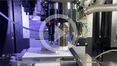
“A metal 3D printed tool means we can do product development with production-quality parts and potentially [let a company] go to market in just a few weeks,” Oles says. Additive molds Alba Enterprises has used have been 3D printed in steel via laser powder bed fusion, and via the flowable metal paste TrueShape process from Mantle, both of which were used successfully for design iterations of the ReelView connector. (The final mold was made by Mantle.)
The injection molding process for the connector is overmolding. That is, plastic is molded around existing elements placed into the mold. “We have to make the part without damaging the electronics,” Oles says. This is part of the challenge. Another part of the challenge simply related to the way connector designs would have to be validated — in use. No digital simulation was sufficient to arrive at a design, because the part would need to be tested in the water, by anglers, according to the various potentially rough or careless ways an angler might put it to use. Alba Enterprises General Manager Michael Dalrymple led the project within Alba and performed the engineering work for each iteration.

Michael Dalrymple (right), general manager for Alba Enterprises, led the mold engineering work for the ReelView connector development. Here he explains the overmolding solution to the author.
Alinger says, “The internals we’re molding around are very delicate. That affects the way we gate the tool. Then there are injection machine settings such as temperature and pressure. To tune the process, those things are knobs we needed to turn. And then the actual outside geometry of the part is also something that evolved over time.”
One important change to the outside geometry was this: The team discovered the connector needs a stress relief, a sleeve to protect the cable where it meets the connector body. Because this sleeve would be pliable while the connector housing is rigid, a different material was needed. ReelView and Alba Enterprises’ solution was to make this stress relief as a separate piece, added to the components being overmolded. At high volumes, the piece might make sense to mold, but the initial run was made through 3D printing instead. Because of the need for a tight, waterproof seal, dimensional precision was important. The stress relief was 3D printed by B9 Creations in the company’s Resilient-Silicone elastomer on its fine-resolution photopolymer DLP (digital light processing) AM system.

The overmolding setup is delicate, and this is one of the important considerations. Placed into the mold prior to molding are the internals of the connector plus the stress relief for the line. The stress relief is a separate 3D printed component.
Overmolding thus involves placing the connector’s internal elements and the 3D printed stress relief into the 3D printed mold. Holding these elements in the mold is nontrivial, because of the vertical orientation of the two halves of the mold in the Babyplast machine. In a high-volume production application for this part, the molder would find a more automated solution, but to make the connectors at the volume ReelView will need to satisfy its initial market entry, Alba was able to employ an off-the-shelf adhesive.
Oles says, “Scotch tape has a thickness that is dimensionally repeatable.” Machining just enough relief into the mold leaves clearance for a piece of tape to both hold the line in position and sufficiently seal the mold. (Not every valuable solution needs new technology.)
It has taken five iterations of the mold design to arrive at a reliable, compact connector design, reliably produced within the compact injection molding machine. But this number of iterations is not the important point.
The more meaningful point is this: ReelView had no idea how many mold design iterations would be needed.
3D printed tooling was the enabler not because it offered a sufficiently fast and economical way to get a series of five molds, but because it offered the way to keep on making mold after mold, for as long as it took, without knowing which of these molds might prove to be the production tool. If ReelView’s inventors had lacked this freedom, it is unclear how they would have proceeded toward their connector design, or how much more time they would have spent on getting there.
Updated and republished from Additive Manufacturing Media.
More From This Author
Peter Zelinski reports on the advance of 3D printing for industrial production as editor-in-chief of Additive Manufacturing Media. Find his work in Additive Manufacturing magazine, in The BuildUp newsletter, and on The Cool Parts Show, which he co-hosts. SUBSCRIBE HERE
Related Content
Three Key Decisions for an Optimal Ejection System
When determining the best ejection option for a tool, molders must consider the ejector’s surface area, location and style.
Read MoreBack to Basics on Mold Venting (Part 1)
Here’s what you need to know to improve the quality of your parts and to protect your molds.
Read MoreOptimizing Pack & Hold Times for Hot-Runner & Valve-Gated Molds
Using scientific procedures will help you put an end to all that time-consuming trial and error. Part 1 of 2.
Read MoreWhat You Need to Know About Leader Pins and Bushings
There’s a lot more to these humble but essential mold components than you might suspect. Following the author’s tips could save much time, money and frustration.
Read MoreRead Next
Video: Mold Base for Product Development With 3D Printed Molds
Alba Enterprises created a mold base to match the needs and pacing of product iteration using mold tooling made via additive manufacturing
Read MoreRekkie AR Ski Goggles Made Possible With 3D Printing: The Cool Parts Show #53
When the electronics enclosure key to these AR goggles proved difficult to mold, 3D printing allowed the inventors to keep the complexity — while also making improvements for assembly and user experience.
Read More3D Printing Molds With Metal Paste: The Mantle Process Explained (Video)
Metal paste is the starting point for a process using 3D printing, CNC shaping and sintering to deliver precise H13 or P20 steel tooling for plastics injection molding. Peter Zelinski talks through the steps of the process in this video filmed with Mantle equipment.
Read More


