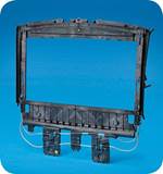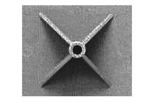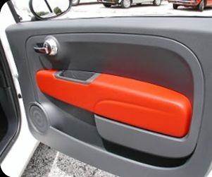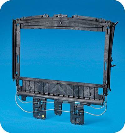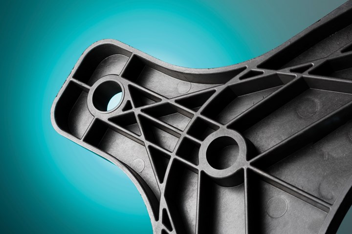
One of the main differences between molding unmodified resins and running short-fiber reinforced compounds is shrinkage behavior. Fiber alignment during flow can cause anisotropic shrinkage and risk of warpage—a risk that increases with fiber loading and flow length. (All images courtesy of Avient Corp.)
Short glass or carbon-fiber reinforcements can be used in virtually any base polymer to create a compound with an enhanced strength-to-weight ratio and improved mechanical properties, such as better stiffness and wear performance. The improvements in strength result from the weaker polymer transferring load stress to the stronger reinforcing fibers. Strong, lightweight, corrosion-free glass- or carbon-fiber composites are good candidates for metal replacement and for demanding applications in such industries as sporting goods and marine infrastructure.
In Part 1 of this two-part series, we explored the particular benefits and challenges of molding long-fiber reinforced thermoplastics. Short fiber-reinforced polymers, while highly versatile, also present some challenges. They may not be suitable for applications requiring a resin-rich surface and glossy finish, because the fibers create a texture that is particularly evident in nylons such as PA6 and PA66. Furthermore, because the fibers do not absorb colorant, they can adversely affect or limit the appearance of the part. In the case of carbon fiber, which creates a mottled look, color choices for a part are usually restricted to dark gray and black to disguise this effect.
However, the most significant differences between short-fiber reinforced materials and their unreinforced counterparts pertain to processing, primarily due to changes in material properties and molding behavior introduced by the fiber. Part 2 of our series focuses on short-fiber-reinforced polymers, presenting factors to consider when molding these materials and offering practical tips on what to do and not to do.
Short Overview of Short Fibers
Short-fiber-reinforced polymers are produced by melt blending chopped fibers with a resin using a compounding extruder. Glass fibers are typically about 5 mm or 3/16 in. long, and carbon fibers are 6 mm or 1/4 in. long. The compounded material is then extruded into a strand and pelletized. This is unlike the process used for long-fiber-reinforced polymers, which are manufactured using pultrusion to produce a continuous-fiber roving that is then chopped to the desired length. Because it is simpler to manufacture short-fiber compounds, they are typically less expensive than their long-fiber counterparts.
Glass-fiber percentage loading by weight can be up to 60% and carbon-fiber loadings up to 50%, but in both cases the fibers eventually begin to overwhelm the resin matrix and cause a decrease in properties.
Within the short-fiber category, glass fibers are less expensive than carbon fibers, which have a higher price tag thanks to their production costs. Carbon fiber does deliver superior mechanical properties, providing stiffness that is four to five times greater than glass fiber. This is one reason why it is often a top choice for metal-replacement applications when lightweighting is required.
Glass-fiber percentage loading by weight can be higher (up to 60%) than carbon-fiber loadings (up to 50%), but in both cases the fibers eventually begin to overwhelm the resin matrix and cause a decrease in properties. These percentages broadly apply to widely used resins such as polypropylene (PP) and nylon (polyamide or PA). Some materials, including high-temperature resins, will only tolerate lower fiber percentages before performance degradation begins.
Short-fiber reinforced polymers are suitable for injection molding, compression molding and extrusion. Semi-crystalline materials are more commonly reinforced than amorphous polymers, in part because amorphous resins generally get a lower boost in mechanical properties from the fibers. Popular base resins that can be reinforced with short fibers include nylons, polyolefins and engineering thermoplastics.
Consider the Shrinkage
One of the main differences between molding unmodified resins and running short-fiber reinforced compounds is shrinkage behavior. Although short fibers are randomly distributed within the pellet, when the pellets are melted during the molding process, their fibers line up parallel to each other in the flow direction during mold filling. During cooling, the fibers resist shrinkage in that flow direction but allow it in the cross-flow direction. This anisotropic shrinkage can lead to warpage. The higher the fiber loading and/or the longer the part length, the greater the risk of warpage. In contrast, unreinforced polymers tend to shrink evenly in both directions.
Although tools designed for unreinforced resin can be used for fiber-reinforced materials, changes in processing parameters are usually necessary. For instance, a cooler mold will freeze the orientation of the fibers, not allowing as much shrinkage to occur and resulting in less warpage. A lower mold temperature will also allow the part to be released faster without causing deformation upon ejection. An exception to the process of freezing orientation occurs when the part experiences elevated temperatures after processing. Higher temperatures can allow the polymer chains to relax, which may result in warpage behavior after molding.
Warpage or deformation during cooling is also more common in thin-wall parts, although thick-wall parts are not immune to it. Of course, shrinkage during cooling is necessary to allow parts to be ejected from the mold. This requisite cooling only causes a problem when shrinkage is inconsistent or unplanned. Sometimes parts can be designed to account for warpage. One approach is incorporating “windage” or reverse distortion into the tool so that when warpage occurs the final part shape is corrected.
Alternatively, leaving the part in a hotter mold for a longer period will help reduce warpage by allowing the polymer chains to relax while the part is held in shape by the tooling. However, molders may not choose this method because it increases cycle time.
Contrary to popular belief, short fibers are harsher on tool steel than long fibers.
Mold Materials & Design
Since reinforcing fibers are abrasive, they will erode the surface of the mold over time. The ends of the short-fiber filaments, which are scattered throughout the pellet, act like needles that impact the steel at different angles. Contrary to popular belief, short fibers are harsher on tool steel than long fibers. That’s because there are fewer ends in long fibers with the same weight percentage as short fibers.
For this reason, when running short-fiber materials, it is recommended to use a harder mold steel, such as H-13, a chromium molybdenum hot-work steel; or P-20, a low-alloy steel. It is also advisable to add some type of hard plating to the cavity surface.
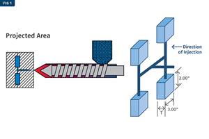
When it comes to tool design, radiused (arc-shaped) runners are advisable to avoid 90° angles that can break the fibers. Sharp, 90° turns without fillets or radii should also be avoided. Furthermore, using a full-round runner eliminates dead flow zones, or areas where a solidified layer of plastic does not permit the full volume of flow. All other runner shapes have these areas.

FIG 1: Some runner shapes are better than others when it comes to molding short-fiber reinforced materials. Full-round runners are best.
Gates should be located in areas that will not interfere with fiber orientation, which is crucial for optimizing strength and stiffness. The ideal location for gates is at the end of the part. This is contrary to techniques often employed with unmodified plastics, where a gate might be placed in the center of a part to balance fill. Also, the gates should be sized generously (avoiding pin gates) to accommodate the greater viscosity of the fiber-reinforced resin and ensure complete mold filling. Recommended gate types include fan gates, tab gates and edge gates.

Adding glass fibers diminishes weld-line strength because the fibers are unable to cross over between the intersecting flow fronts and provide strength at the point where they meet.
Another key consideration is weld lines. Adding glass fibers diminishes weld-line strength because the fibers are unable to cross over between the intersecting flow fronts and provide strength at the point where they meet. If they simply hit each other without intermingling, mechanical performance will be limited to the properties of the resin matrix. And the higher the fiber loading, the fewer polymer chains that are available to entangle at the weld line.
Although many other factors affect the weakness or strength of weld lines, gating once again plays a key role. Gates should be carefully placed to avoid the formation of weld lines at critical structural points, such as an area of high stress during part use. The gate location should enable the two flow fronts to merge easily and continue to flow beyond the weld line.
Molding Equipment
The need to minimize fiber breakage, plus the higher viscosity of materials with high fiber content, require some adjustments to the molding equipment. For example, a larger-than-normal nozzle orifice (7/32 or 9/32 in.) can ensure unrestricted material flow. Also, a reverse-taper nozzle is better for fiber-reinforced materials. A reverse-taper nozzle does not have the same restrictions as a general-purpose nozzle, so it can help reduce the overall shear force applied to the material. Lower shear helps to maintain the fibers’ length and prevent them from turning into a powder. It also helps reduce the chances for polymer degradation from excessive heat.
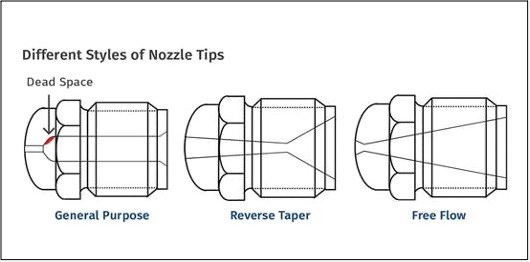
FIG 2: A reverse-taper nozzle tip is recommended for processing short-fiber-reinforced materials.
Another approach to lowering shear is using a low-compression screw that turns at a lower rate (50-199 rpm) with lower backpressure (50-200 psi).
A flatter-profile screw creates the highest temperature at the nozzle and will provide less temperature difference along the five heat zones of the screw barrel. Alternatively, the hottest zone of a reverse-profile screw is at the feed location. A reverse-profile design is sometimes used with long fiber-reinforced compounds so the polymer melts from heat instead of from shear forces produced by screw’s rotation. These shear forces cause fiber attrition. Further, this type of screw may be used when excessive drooling occurs at the nozzle.
A reverse-profile design is sometimes used with long fiber-reinforced compounds so the polymer melts from heat instead of from shear forces produced by screw’s rotation, which cause fiber attrition.
Processing Parameters
As with all fiber-reinforced compounds, retaining fiber length during processing is essential for maximizing material performance in molded parts. Reductions in fiber length can occur throughout the molding process and are tied to factors such as undersized gates, as mentioned earlier. Unhindered flow can help preserve the integrity of the fibers. A few factors to remember:
• Drying: Drying requirements depend on the type of resin and whether it readily absorbs moisture.
• Conveying: Avoiding sharp corners or impacts while conveying the pellet to the molding equipment can help protect fiber length.
• Injection speed: Slower than 25.4 mm (1 in.) per second is ideal for minimizing shear and fiber breakage, although any speed less than 3 in./sec should suffice. On the other hand, injecting too slowly can result in premature freezing-off of the gates or other areas of thin-wall parts, causing a short shot.
• Mold filling: Fill the mold to 98% in the injection phase (compared with 95% for most unreinforced resins) and then fill the remaining 2% in the pack phase.
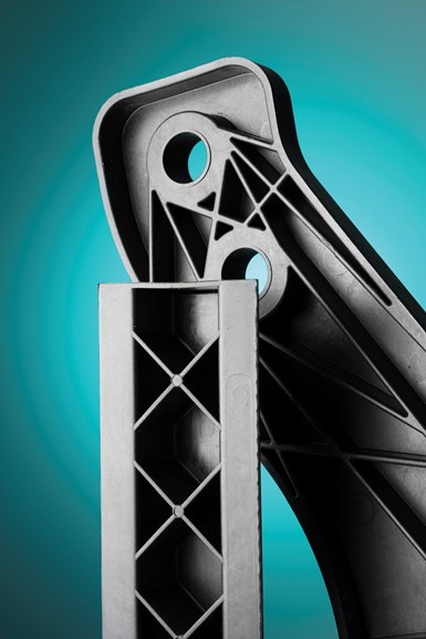
Very thin walls can increase shear forces during mold filling and cause fiber breakage. Thin walls can also make the fibers more visible in the finished part.
Part Design
Like processing, part design should play to the strengths and avoid the weaknesses of short fiber-reinforced materials. Considerations include wall thickness: very thin walls can increase shear forces during mold filling and cause fiber breakage. Thin walls can also make the fibers more visible in the finished part. It is advisable to avoid walls thinner than 0.762 mm (0.030 in.), particularly in parts with a longer flow lengths.
Going Long on Short Fibers
Fiber-reinforced polymer compounds are a huge and growing market, with an estimated one-third of polymers compounded with fiber and/or other particulate reinforcing additives, thanks to high demand from the transportation, electrical, electronics, wind-energy, pipe and tanks industries. Carbon-fiber reinforced composites are expected to grow at an average rate of more than 8% from 2019 to 2024. Increasing use of carbon-fiber materials by the aerospace and automotive industries is a major factor; however, high cost and limited capacity are working against stronger gains.
The popularity of short-fiber reinforced materials makes it likely that many molders will work with these materials. As a starting point, the material can be processed in existing equipment using standard parameters. The results may be acceptable if the goal is to achieve an increase in mechanical properties. Following the recommendations in this article can help optimize part strength and stiffness.
Editor’s Note: Part 1 of this series addressed long-fiber processing fundamentals and best practices, including practical tips and guidance on maintaining fiber length and deriving maximum advantages for demanding applications.
ABOUT THE AUTHOR: Zachary Alderman, senior ADTS engineer, Avient Corp., is an experienced application development engineer who provides application engineering support to Avient’s West Coast sales team. Skilled in Moldflow and SolidWorks, Alderman has a deep knowledge and understanding of injection molding and plastics materials. Alderman has a bachelor’s of engineering (B.E.) in plastics and polymer engineering technology/technician from Pennsylvania State University-Erie.
Related Content
How to Reduce Sinks in Injection Molding
Modifications to the common core pin can be a simple solution, but don’t expect all resins to behave the same. Gas assist is also worth a try.
Read MoreIs There a More Accurate Means to Calculate Tonnage?
Molders have long used the projected area of the parts and runner to guesstimate how much tonnage is required to mold a part without flash, but there’s a more precise methodology.
Read MoreWhat to Look for in High-Speed Automation for Pipette Production
Automation is a must-have for molders of pipettes. Make sure your supplier provides assurances of throughput and output, manpower utilization, floor space consumption and payback period.
Read MoreUnderstanding the Effect of Pressure Losses on Injection Molded Parts
The compressibility of plastics as a class of materials means the pressure punched into the machine control and the pressure the melt experiences at the end of fill within the mold will be very different. What does this difference mean for process consistency and part quality?
Read MoreRead Next
The Long and Short of It (Part 1)—Tips for Molding Long Fiber-Reinforced Polymers
In Part 1 of this series, we address long-fiber processing fundamentals and best practices, including practical tips and guidance on maintaining fiber length and deriving maximum advantages for demanding end applications. Part 2 will provide the same information for short-fiber materials.
Read MoreLong-Glass Fiber Reinforced Polyolefin Sheet for Automotive and More
Germany's Renolit is now in North America and thriving in automotive, building & construction, and furniture.
Read MoreSunroof Module Is All Short-Glass PP
The first fully integrated automotive sunroof module made entirely of short-glass PP replaced long-glass PP and short-glass ASA/PBT on the 2010 Cadillac CTS.
Read More


