The Scale-Up Conundrum
Extrusion Know How
There are many methods used to determine scale-up based on output, but most designers do not scale the melting requirement along with the output.
When designing an extruder screw, scale-up is one of those head-scratching areas. There are many methods used to determine scale-up based on output, but most designers do not scale the melting requirement along with the output. Instead, they tend to use a simple ratio for the flight depths and stick with the same number of flights in each section.
There are so many variables to consider when scaling up, and they all change at the same time, making manual calculations difficult to do. The interdependence of the variables doesn’t simplify scale-up all that much, even with computer simulation.
Cost and time issues have made it necessary for designers to develop a simpler method than full computer simulation for much of screw design and manufacture. There are some shortcuts that apply—assumptions about the distribution of energy going into the polymer, and a simplification of the classic melting theory into a bulk energy transfer that can approximate the melting rate with reasonable accuracy and in a reasonable time frame. But it still requires a good understanding of how the energy is distributed and of polymer rheology to get usable answers. Melting capacity requires knowledge of the polymer thermal properties, the mass flow, screw geometry, shear rates, the consistency index, and the power-law coefficient.
When increasing screw diameter, the output increases at a rate greater than the square of the diameter because of increasing channel depth with increasing diameter (assuming constant head pressure). However, the melting area increases proportionally to the square of the diameter. Simply using the same number of turns in the melting section for a scale-up in screw size results in restricting the melting capacity. The same is true when scaling up for greater L/D, or even when the screw is simply deepened for more output. This can become a problem leading to rapid screw wear, surging, and poor melt quality, particularly with semi-crystalline polymers.
Although melting can occur in all sections of the screw, the bulk of it normally occurs in the compression or barrier section. In conventional screws, some solids typically exit the compression section unmelted due to eventual solids-bed breakup, and that percentage has to be considered based on the polymer characteristics. Determining the correct percentage requires further assumptions and considerable trial-and-error experience. For barrier screws, your best bet is to assume all melting occurs in the solids channel.
Conductive melting is ineffective with polymers except in small-diameter extruders or at very low screw speeds, because polymers are excellent insulators and do not absorb heat readily. Consequently, it greatly simplifies the calculation in the melting section to assume any conducted heat flow in/out between the barrel and the polymer is minimal and constant.
This typically introduces only a small error, except in cases involving exceptionally aggressive barrel cooling. With semi-crystalline polymers, conductive melting is further restrained by the requirement for the breakdown of the crystallinity, or the heat of fusion. Amorphous polymers allow much more latitude in the melting-rate calculations because the polymers will often be soft enough to pass through restrictive areas of the screw below their typical flow temperature.
Most often, the barrel temperatures are lower than the melt film temperature at the barrel wall in the melting section because of the high shear rates in the film and over the flights. This reduces the melting rate due to absorption of energy from the film because of the higher thermal conductivity of the barrel. Consequently, actual melting rates are most often lower than calculated rates, necessitating some over-design.
In the absence of polymer training and data to calculate melting rates, a simple rule for scale-up is to maintain the ratio between the area for melting and the output for a particular polymer with a screw design that works well. If you increase the output 50% you should increase the melting area 50%. This requires only some simple geometric calculations of area and estimation of the new output versus the present one.
However, each polymer has a different ratio between output and melting area, so a separate ratio must be developed for every polymer for a new screw design or for troubleshooting. Consideration must also be given to the width of the screw flight and clearance, as shearing of the polymer in the clearance can account for 10% to 30% of the power entering the polymer. This is treated in the same way as the energy in the channel and is simply added to the power from the channel. Keeping the same proportion of flight width and flight clearance between screw diameters will avoid over- or under-affecting the melting rate.
There’s no single ratio that can simplify the determination of melting capacity of various polymers. But once yours has been established it can be used for scale-up, troubleshooting, and new screw design. It takes lots of time to collect and analyze all the data, but once completed it’s a big time saver.
Related Content
How Screw Design Can Boost Output of Single-Screw Extruders
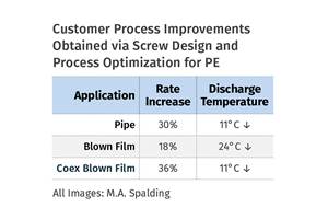
Optimizing screw design for a lower discharge temperature has been shown to significantly increase output rate.
Read MoreRoll Cooling: Understand the Three Heat-Transfer Processes
Designing cooling rolls is complex, tedious and requires a lot of inputs. Getting it wrong may have a dramatic impact on productivity.
Read MoreUse Interactive Production Scheduling to Improve Your Plant's Efficiencies
When evaluating ERP solutions, consider the power of interactive production scheduling to effectively plan and allocate primary and secondary equipment, materials and resources on the overall production capacity of the business and conclude that this is a key area that cannot be overlooked.
Read MoreUnderstanding Melting in Single-Screw Extruders
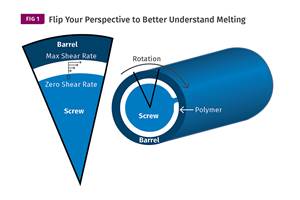
You can better visualize the melting process by “flipping” the observation point so the barrel appears to be turning clockwise around a stationary screw.
Read MoreRead Next
For PLASTICS' CEO Seaholm, NPE to Shine Light on Sustainability Successes
With advocacy, communication and sustainability as three main pillars, Seaholm leads a trade association to NPE that ‘is more active today than we have ever been.’
Read MoreBeyond Prototypes: 8 Ways the Plastics Industry Is Using 3D Printing
Plastics processors are finding applications for 3D printing around the plant and across the supply chain. Here are 8 examples to look for at NPE2024.
Read MoreMaking the Circular Economy a Reality
Driven by brand owner demands and new worldwide legislation, the entire supply chain is working toward the shift to circularity, with some evidence the circular economy has already begun.
Read More
.jpg;width=70;height=70;mode=crop)


