What We Didn't Know About Dielectric Properties of Plastics
With speed at a premium, computers and other electronic devices are moving to higher frequencies.
With speed at a premium, computers and other electronic devices are moving to higher frequencies. Many systems now operate in the 1 to 10 GHz range, while new applications will run at frequencies as high as 20 GHz.
Understanding how the materials of construction in such devices perform at these frequencies is a challenge facing designers. For plastics in electronics, awareness of the subtle effects of polymer chemistry, additives, part thickness, and flow patterns is essential to optimizing resin selection and part and mold design.
Plastics are generally considered insulators, but they can transmit some electrical energy at higher frequencies. The effectiveness of a material as an insulator is usually measured by quantities like dielectric constant (Dk) and dissipation factor (DF). A significant body of data has been developed for how these parameters vary in plastics in the megahertz range. Relatively little data currently exists for plastics’ dielectric behavior at frequencies above 1 GHz.
Many variables affect a plastic’s dielectric constant, including the frequency used, the filler and additives it contains, part thickness, and environmental conditions such as moisture. To illustrate how Dk and DF vary within a class of plastics, this article summarizes recent high-frequency test results on liquid-crystal polymers, often used in electronics.
Key dielectric properties
| Table 1-Dielectric constants of Different Materials* |
|
| Material Vacuum Air Typical Plastics Natural Rubber Glass Mica Aluminum Oxide (Alumina) Water |
Dk 1.000 1.0006 2 to 5 3 4 to 7 5 to 9 8 to 10 80 |
| *Values supplied by Joseph P. Curilla, Electronics Consulting Laboratory. | |
Two of the most important parameters describing plastics’ dielectric behavior are dielectric constant and dissipation factor. Dk addresses how well an insulator stores electrical energy so as to isolate electrical elements from each other and the ground. The Dk of a substance is the ratio of two capacitance values: that of a capacitor made with the substance as the dielectric divided by the capacitance when a vacuum or air serves as the dielectric. This quantity is important in designing connectors, electronic circuits, microwave devices, RF transmission lines, antennae and waveguides.
The more conductive a material, the greater its Dk. Vacuum and dry air have very low dielectric constants (Table 1). By definition, their Dk is equal to or approaching 1.0. Water has a very high Dk, while many metal oxides and ceramics, mica, glass, and plastics have moderate to low Dk values.
Good dielectrics also tend to have a low dissipation factor (DF). That is, they do not let the charge they hold dissipate easily and they lose little energy as heat as the electric field reverses rapidly at high frequencies. DF represents the inefficiency of dielectric materials. It is the ratio of the loss factor (a measure of all losses in a dielectric) to the dielectric constant of that material.
Dk is a central design variable in tuning an electronic structure to a desired impedance. Variations in Dk as small as 0.1 in a structure can make a difference in how a device performs. As systems grow more compact, the need for low Dk becomes more vital.
| Table 2-Thermoplastic Dielectric Constants* | |
| Resin PTFE Polypropylene Polyethylene Polystyrene ABS Polycarbonate PET PBT PPS LCP Acetal Copolymer Nylon 66 |
Dk 2.1 2.2 2.3 2.4 2.6 3.0 3.0 3.1 3.2 3.5 3.7 4.6 |
| *Values supplied by Joseph P. Curilla, Electronics Consulting Laboratory. | |
There is thus a compelling need for a comprehensive understanding of the dielectric constants of plastics at frequencies from 1 to 20 GHz. This body of knowledge should also account for the many material, design, and end-use variables that affect Dk, so manufacturers can create the most effective designs.
Testing of LCPs
Dk in plastics is directly related to the polarizability of the polymer (Table 2). For example, PTFE and polypropylene have very low Dk levels, and nylons fall at the high end of the range. Dk for liquid-crystal polymers (LCPs) falls in the middle to high end of the range for plastics but is among the lowest in the class of high-temperature thermoplastics.
LCPs are a family of wholly aromatic polyesters frequently used in thin-walled, injection molded parts, such as complex connectors having high pin densities, because of their excellent flow and strength in narrow wall sections. LCPs are also used in high-frequency, multilayer, printed-circuit boards and in chip modules and chip carriers.
Unfilled LCPs typically have a Dk between 3 and 4, depending on the polymer’s chemistry, and a low loss factor at higher frequencies. They are often superior to traditional dielectrics in high-speed digital devices and have excellent electrical properties in copper-clad films.
How testing was done
A recent study explored a number of variables to see how they affect the dielectric properties of LCPs at frequencies at and above 1 GHz. The study involved Dk and DF measurements at five frequencies (1, 2.5, 5, 10, and 20 GHz) for several grades of Ticona’s Vectra LCP and another commercial LCP. The Vectra grades have similar monomer compositions and are markedly different in composition from the other commercial LCP. Testing explored not only the effects of resin type, but also reinforcing fibers, conductive additives, wall thickness, and molecular orientation. Moisture was not included in the study because LCP absorbs almost no water. This parameter might be important for polymers that take up significant amounts of water. All grades in the study were black, except one that was only available in natural color. Each grade was molded in three plaque sizes:
- 60 x 60 x 4 mm using a 50 x 2 mm gate.
- 60 x 60 x 2 mm using a 60 x 1.5 mm gate.
- 80 x 80 x 1 mm using an 80 x 0.8 mm gate.
Dk testing was done by an independent testing laboratory (Electronics Consulting Laboratory) and followed Test Method B: “Resonant Cavity Perturbation Technique” as defined in ASTM D2520-01, “Standard Test Methods for Complex Permittivity (Dielectric Constant) of Solid Electrical Insulating Materials at Microwave Frequencies and Temperatures to 1650 C.”
This test method measures the resonant frequency and quality factor of a resonant-cavity test fixture with the test specimen in place and without it. All specimens were preconditioned at 23 C and 50% relative humidity. Dk and DF were computed from these measurements and the dimensions of the specimen. The test has an accuracy of ±1% for Dk and ±5% for DF. All tests were done in triplicate.
ASTM Method B limits the volume of the material evaluated at each frequency to ensure accuracy. As a result, the specimens used had different thicknesses depending on frequency. For testing at 1 and 2.5 GHz, samples were taken from the 4-mm plaques; for 5 and 10 GHz, they were from 2-mm plaques; and for 20 GHz, they were from 1-mm plaques. Specimens were prepared so the electric field during testing was parallel to the melt-flow direction of the sample.
Effect of composition
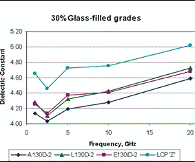
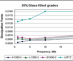
Dielectric constants of three grades of Vectra LCP and another commercial LCP demonstrate the effects of polymer composition. Resins filled with 30% glass fiber were used since they are often the first choice for electrical and electronic applications. Vectra L130D-2 and E130iD-2 LCP have similar dielectric behavior. The lowest Dk and DF were obtained for Vectra A130D-2 LCP (Figs. 1 and 2). The other commercial LCP, which has a different monomer composition (LCP “Z”), resulted in substantially higher Dk and DF.
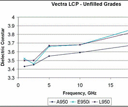
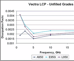
To confirm that the trend was based on differences in polymer chemistry, the Dk and DF for three unfilled grades of Vectra LCP were determined (Figs. 3 and 4). The unfilled polymers show the same trend as did the glass-filled grades.
The unfilled polymers A950, L950, and E950i have a Dk of about 3.45 to 3.5 at 1 GHz. Those values increase with frequency to between about 3.7 and 3.85 at 20 GHz (Fig. 3). The related glass-filled materials have Dk values from about 4.15 to 4.25 at 1 GHz and 4.6 to 4.7 at 20 GHz (Fig. 1). This increase is expected since glass has a higher Dk than LCP.
| Table 3-Dielectric Properties Vs. Molecular Orientation (Vectra E130iD-2 @ 1 GHz) |
||
Dk Std. Dev. DF Std. Dev. |
Flow Direction 4.26 0.0058 0.0061 0.0001 |
Transverse Direction 3.95 0.0424 0.0074 0.0001 |
| *Values supplied by Joseph P. Curilla, Electronics Consulting Laboratory. | ||
The differences in Dk for different grades give designers some leeway in choosing a material to meet the needs of an electronic structure. Vectra A resin had the lowest Dk in both neat and glass-filled grades. Vectra L and Ei resins also had relatively low Dk values and are best used when higher temperature resistance is needed. The dip in Dk at 2.5 GHz seen with both unfilled and glass-filled resins is unexplained and appears to be characteristic of the material because it did not occur in a PTFE control sample.
Vectra LCP resin A also had the lowest dissipation factor (Figs. 2 and 4). At 1 GHz, the DF of unfilled Vectra A resin was less than half that of the other two grades tested (0.0019 vs. about 0.0042). At 20 GHz, DF for the various unfilled grades was practically equivalent at about 0.0022. Glass-filled grades of Vectra LCP ranged between about 0.004 and 0.006 at 1 GHz and about 0.006 and 0.007 at 20 GHz. The commercial LCP (“Z” resin) outside the Vectra family had much higher values.
Conductive carbon black is often added to improve dissipation of static electricity. Measurement of Vectra LCP A422 formulated for this purpose showed that its Dk varied from 9.5 at 1 GHz to nearly 15 at 20 GHz. These values are about two to three times higher than those for the 30% glass-filled grades tested. DF values in the carbon-filled grades were about 10 times greater than those of the glass-filled grades.
Adding materials with lower Dk can also reduce the Dk of Vectra LCPs. When PTFE replaced glass fibers, Dk decreased since PTFE has a lower value than both glass and LCP. For instance, a grade containing 50% PTFE had about a 15% lower Dk than a 30% glass-filled LCP.
Effect of thickness & flow
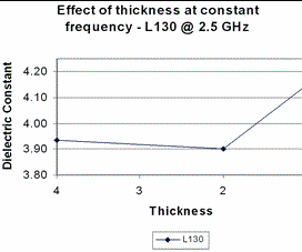
The study also found that part thickness affects Dk and DF. When thickness was varied at a fixed frequency of 2.5 GHz, Dk remained nearly steady as thickness fell from 4 to 2 mm, but rose by about 0.2 units in going from 2 to 1 mm (Fig. 5). DF also was nearly steady at about 0.0049 between 4 and 2 mm thickness and then fell to about 0.00435 at 1 mm. This effect may be due to the changing relationship between the skin and the core, since 1-mm samples have a higher percentage of polymer chains oriented in the flow direction.
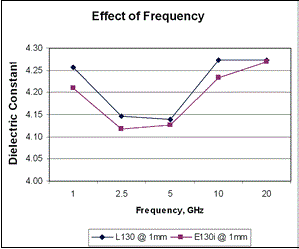
It is well known that the thickness of an LCP component affects its mechanical properties due to LCP’s skin-core effect. Since the standard ASTM procedure requires a different sample size for each frequency, further studies were done to understand the effect of frequency on Dk and DF in parts having a constant thickness. The Dk of a 1-mm sample was about 0.1 unit lower at 2.5 and 5 GHz than it was at 1, 10, and 20 GHz (Fig. 6). DF was more consistent, varying between 0.0044 and 0.006 at 1 GHz and between 0.0044 and 0.005 at 2.5 GHz. DF values at 20 GHz were about 0.65.
In addition, the dielectric properties for Vectra LCP E130iD-2 were measured using an electric field that was parallel to the flow of the resin when it was molded (standard conditions) and perpendicular to flow (transverse). At 1 GHz, Dk was 3.92 in the transverse direction and 4.26 in the flow direction, while DF was 0.0075 in the transverse and 0.0061 in the flow direction (Table 3). This shift in values indicates that tool design and how a part fills the mold cavity should be taken into account when creating precision electronic components for use at high frequencies.
Kent Regnier is principal engineer with the Molex Connector Products Div. in Lisle, Ill.
Michelle Brand, Ticona sales and market-development manager for the Vectra LCP business, is based in Woodstock, Ill.
Sandra Osmun is a product specialist in the Vectra LCP technical group. Dan Palangio, is an Engineer II and a member of the Vectra LCP technical team. Dr. Clay Linstid is Vectra LCP global technology leader. All three are located at Ticona’s U.S. headquarters in Summit, N.J
Related Content
How to Optimize Color Evaluation of Recycled Plastics
The right color measurement instrument and good working methods will minimize variability in color evaluation of PCR.
Read MoreDatacolor Acquires Matchmycolor
The acquisition of the specialist in color formulation and communication software further expands Datacolor’s global industry presence in color management.
Read MoreRedesigned Laser Scanner Boasts Improved Accuracy, Resolution, Versatility, and Efficiency
Nikon Metrology’s new LC15Dx is ideal for efficient measurement and inspection of manufactured components including intricate plastic parts.
Read MoreBrabender GmbH Bought By Austrian Measurement Company
Leading metrology company Anton Paar buys 100-year old firm, known in the U.S. as C.W. Brabender.
Read MoreRead Next
Making the Circular Economy a Reality
Driven by brand owner demands and new worldwide legislation, the entire supply chain is working toward the shift to circularity, with some evidence the circular economy has already begun.
Read MorePeople 4.0 – How to Get Buy-In from Your Staff for Industry 4.0 Systems
Implementing a production monitoring system as the foundation of a ‘smart factory’ is about integrating people with new technology as much as it is about integrating machines and computers. Here are tips from a company that has gone through the process.
Read More


