What's Restricting My Output Rate?
In a single-screw extruder, it could be an improperly designed barrier flighted entry section. Here’s why.
A well-designed screw using a barrier flighted melting section can provide higher rates — up to 20% — and lower discharge temperatures compared to a conventional flighted melting section. When combined with a downstream Maddock mixer, the quality and rate of the extrudate can be optimized for the application, maximizing productivity.
This technology was the first of its kind to use the concept of separating the compacted solid bed from the melt pool as it progressed down the transition section of the screw. A cross section of a barrier melting section perpendicular to the main flight edge is shown in Figure 1. The compacted solid bed is adjacent to the trailing side of the main flight. Melting occurs by dissipating energy in the thin melt film located between the solid bed and the barrel wall.

FIG 1 Schematic for a barrier melting section. The cross section is perpendicular to the main flight. Source: Mark Spalding
The dissipated energy conducts into the solid bed and melts resin at the interface. The molten resin is then conveyed over the barrier flight and into the melt channel. The barrier flight is undercut by about 0.5 to 1.5% of the diameter from the main flights. Thus, for a 6-inch diameter screw, the undercut would be about 0.030 to 0.090 inch. The barrier flight adds a level of dispersive mixing and prevents large solid resin fragments from entering the melt pool.
There are many barrier melting section designs that are used commercially. One of the highest performing designs uses lead lengths equal to the diameter in the feed section and in the meter section. The lead length of the main flight and the barrier flight in the barrier section are increased to 1.25 to 1.40 times the diameter. The lead length is increased to enable a larger total width in section. The width of the solids channel is typically about twice the width of the melt channel. The solids channel is the deepest at the entry and it tapers to a shallow depth at the exit of the section. The melt channel is the opposite with the channel being shallow at the start and the deepest at the exit. As previously stated, there are many versions of the design practiced commercially.
The Rate Controlling Process
For smooth-bore plasticating extruders, the metering channel must be the rate controlling process. A poorly designed barrier section, however, can be the rate limiting step. When this happens, the extruder will run at low specific rates and can cause degraded resin to appear in the product. The specific rate is the rate divided by the screw speed — lb/(hr rpm). The rate restriction can cause portions of the metering section to operate partially filled and at zero pressure. For polyethylene (PE) resins, degradation gels can form in the partially filled portion of the screw. When the gels separate from the screw, they will cause defects in the product (as shown by Figure 2) for a cast film.

FIG 2 Crosslinked PE gel in a cast film.
As an example, a 3.5-inch diameter extruder with a screw designed with a barrier melting section was operating at a specific rate of 3.6 lbs/(hr rpm). The calculated specific rate for the metering section, however, was 5.5 lbs/(hr rpm). Here, the metering channel was not controlling rate. Instead, some feature upstream of the metering section was controlling rate. The extruder was stopped, and the screw was removed hot.
The metering section of the screw is shown in Figure 3. It shows freshly melted resin on the pushing side of the channel. When the screw was first installed, the trailing side of the channel was void of resin, but after continued operation, this side of the channel became stagnant with resin. This pattern of degraded and fresh resin is shown schematically in Figure 4. It took about 13 days of operation to develop the steady-state level of degradation shown in Figure 3. Minor process instabilities would cause a small portion of the degradation to break away from the screw. The downstream Maddock mixer would cause the fragment to break into many smaller fragments, causing a gel “shower” in the film product.

FIG 3 Photograph of the metering section of a screw with a poorly designed barrier flighted entry. The white material is freshly melted LDPE, while the dark material is degraded and crosslinked resin.
The specific rate was reduced from 5.5 to 3.6 lbs/(hr rpm), a reduction of 35%. When the screw was removed from the extruder, compacted solids had formed at the entry to the barrier section. It was these compacted pellets that reduced the flow of material into the barrier section. Moreover, the reduction in specific rate was enough to cause the metering channel to operate partially filled, causing the resin to degrade and the eventual gels in the film product.

FIG 4 Schematic of a partially filled metering channel.
The restriction at the entry of the barrier melting section was caused by a reduction in the width of the channel for solids to flow. As an example, a 2.5-inch diameter screw with an entrance design shown in Figure 5 was rate restricted. For this case, the solids channel width (W2) in the barrier section was 15% narrower than the upstream solids conveying section (W1).

Even though the lead length was increased in the barrier section, the addition of the melt conveying channel reduced the width available for the flow of compacted solids. This barrier flight introduction can restrict flow to the downstream sections of the screw, causing parts of the metering channel to operate partially filled as shown in Figure 3. This restriction can occur even with a lead length in the barrier section that is 1.4 times the diameter.
At the entry, the compacted solid bed must rearrange as it is transferred from the solids conveying channel to the solids channel of the barrier flighted section. If the channel design allows rearrangement, then the extruder will operate at the designed rate. If rearrangement is restricted, the channel pressure increases upstream of the entry.
The high pressure will cause a higher level of energy dissipated from the friction between the surface pellets and the barrel wall, creating an energy flux that conducts through the barrel wall. Sometimes this energy flux is high enough that the barrel zone positioned over the entry will overshoot the set point temperature. During the troubleshooting process, it is always a good idea to see if this zone is overshooting set point or has a higher level of cooling compared to the solids conveying zone.

The rate restriction can sometimes be mitigated by removing metal at the entrance of the melt channel such that some solids are intentionally passed down the melt channel. A photograph of a modified screw is shown by Figure 6b. For reference, a similar screw without the modification is shown by Figure 6a. The barrier flight is removed at the entry down to the core of the melt channel for about the first 1.5 turns. Next the barrier flight should be tapered from the root of the melt channel to full height over the next turn. This mitigation process can be complicated for some commercial designs. Screw designers and fabricators are aware of the problem and the remedy to mitigate it.
About the Author: Mark A. Spalding is a fellow in Packaging & Specialty Plastics and Hydrocarbons R&D at Dow Inc. in Midland, Michigan. During his 39 years at Dow, he has focused on development, design and troubleshooting of polymer processes, especially in single-screw extrusion. He co-authored Analyzing and Troubleshooting Single-Screw Extruders with Gregory Campbell. Contact: 989-636-9849; maspalding@dow.com; dow.com.
Related Content
Three Key Decisions for an Optimal Ejection System
When determining the best ejection option for a tool, molders must consider the ejector’s surface area, location and style.
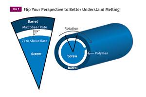
Read MoreUnderstanding Melting in Single-Screw Extruders
You can better visualize the melting process by “flipping” the observation point so the barrel appears to be turning clockwise around a stationary screw.
Read MoreThe Effects of Time on Polymers
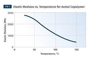
Last month we briefly discussed the influence of temperature on the mechanical properties of polymers and reviewed some of the structural considerations that govern these effects.
Read MoreA Systematic Approach to Process Development
The path to a no-baby-sitting injection molding process is paved with data and can be found by following certain steps.
Read MoreRead Next
Lead the Conversation, Change the Conversation
Coverage of single-use plastics can be both misleading and demoralizing. Here are 10 tips for changing the perception of the plastics industry at your company and in your community.
Read MoreFor PLASTICS' CEO Seaholm, NPE to Shine Light on Sustainability Successes
With advocacy, communication and sustainability as three main pillars, Seaholm leads a trade association to NPE that ‘is more active today than we have ever been.’
Read MorePeople 4.0 – How to Get Buy-In from Your Staff for Industry 4.0 Systems
Implementing a production monitoring system as the foundation of a ‘smart factory’ is about integrating people with new technology as much as it is about integrating machines and computers. Here are tips from a company that has gone through the process.
Read More


