What Is the Right Plastics Joining Process for You: Part 2—Available Technologies
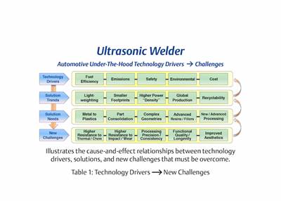
The four primary joining technologies—vibration, clean vibration, infrared, hot-gas/convection—offer different benefits and challenges for different applications.
Vibration welding uses heat energy generated when one part is held stationary while the other part is moved in a linear, back-and-forth motion. The heat generated initiates a controllable meltdown at the interface of the parts. Vibration welding requires that the part interface accommodate the relative motion inherent in the process. Typical motion is 1 mm in each direction for 240 Hz welding and 2 mm in each direction for 100 Hz welding.
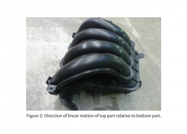
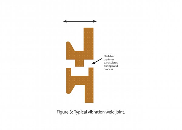
Figure 2 shows an air intake manifold made from PA6 GF30. While the geometry is complex, the parts are designed so that there is a part-to-part orientation that will accommodate the linear motion required by the process. Jagged weld flash and particulates are typical byproducts of vibration welding. “Flash traps” are designed into the parts—Figure3—to contain the flash produced during the weld. However, in some designs, part geometry does not always allow for this method of flash containment.
Infrared welding uses energy that is radiated by gray body emitters mounted on a movable platen. It is a non-contact process in which the parts to be joined are brought close to the emitter platen (approximately 1 mm) as energy is absorbed at the weld interface. The parts are then pressed together, achieving a bond that is controlled during meltdown.
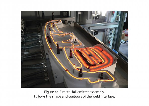
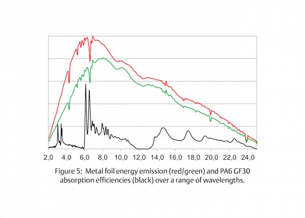
Infrared emitters are typically either glass bulb or metal foil (Fig. 4). To optimize energy absorption in the weld area, the emitters should have an output energy profile that accommodates the absorption efficiency profiles of the many plastics used (Fig. 5). Medium wave emitters have this characteristic and are best for plastics joining.
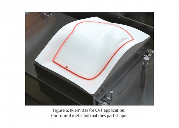
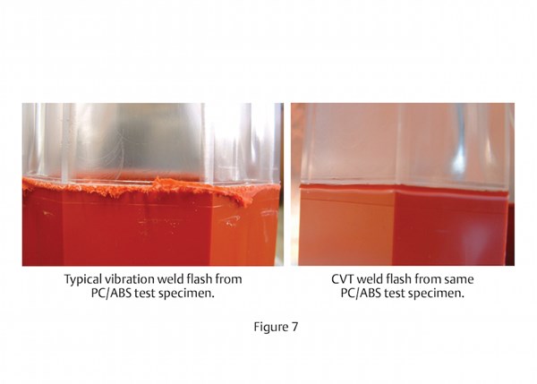
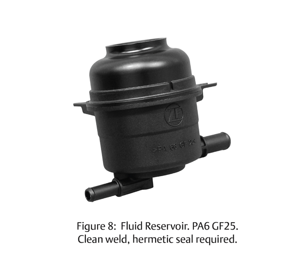
Clean vibration technology (CVT) combines IR preheating (Fig. 6) followed by a vibration weld cycle. The preheat step enables the combined process to bypass the dry friction phase in traditional vibration welding, which generates the common particulate and jagged flash (Fig. 7). In CVT welding, the flash produced is clean and compact, similar to that of IR welding. Figure 8 shows a fluid reservoir requiring a hermetic seal, high strength, and a clean weld joint. Geometry constraints did not allow for the option of flash traps so weld aesthetics were also important.
Laser welding uses energy typically generated by one or more 980 nm laser sources to heat the parts during the weld cycle. Several techniques exist that deliver the laser energy from its source to the plastic parts, including simultaneous, quasi-simultaneous and trace welding. All techniques deploy the concept of through transmission welding, in which the parts are clamped together as the laser energy is transmitted through one part and absorbed by the second part at the mating interface. The absorbed heat is conducted across the part interface, thus achieving a controlled melt in both parts.
Laser welding accommodates highly complex parts, achieves high-strength welds, and, in the case of simultaneous laser welding, has very fast cycle times. The resulting weld joint has very little flash and virtually zero particulate. No relative motion or high-temperature heat sources are required during the weld process, so parts with delicate internals are often candidates for this technology. Laser welding requires parts with good dimensional tolerances and also requires one part to have a higher transmission/absorption ratio (at 980 nm) relative to the other. This is usually accomplished by using selective colorants in the parts.
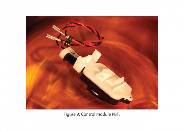
Figure 9 shows a laser welded electronic control module that has delicate internals and a very thin wall, creating very little room for a weld joint.
Hot gas (convection) welding uses the energy in electrically heated air that is directed out of an array of nozzles mounted on a movable platen. It is a non-contact process in which the parts to be joined are brought close to the air nozzle platen (<1 mm) for a preset amount of time while the heated air is directed toward the weld joint area. The parts are then pressed together, thereby achieving a controllable welded joint. Instead of using heated air, exhaust gas from natural gas or methane combustion may be used as the heating medium. This reduces the amount of oxygen in the hot gas, which reduces heating time. The hot gas welding process has advantages similar to IR welding, but it requires a consumable gas if the natural gas or methane approach is used. Very tight dimensional tolerances of the parts are required in this process.
Other technologies are, of course, available for plastics joining that remain viable for a number of under-the-hood applications. These include hot plate welding, spin welding, and ultrasonic welding. While these processes are not described in-depth here, they are also an important part of an overall technology evaluation for any application.
This is part 2, read part one of Choosing the Right Plastics Joining Process.
About the author: Craig Birrittella holds the position at Emerson as Automotive Segment Manager, Americas, for Branson Ultrasonics, Danbury, Conn. Graduating from State University of New York at Buffalo with a mechanical engineering degree, Craig holds a patent related to using a lens to adapt laser intensity for uniform welding. Emerson is a global manufacturer of Branson Ultrasonics material joining and precision processing equipment. He can be contacted at Craig.Birrittella@Emerson.com.
Related Content
Thin Wall Ultrasonic Bonding Technology for Automotive
NPE2024: Dukane’s new Ultrasonic Thin Wall welding system is well suited for welding applications of PP to PP TD25 painted parts.
Read MoreAdvanced Inspection of Bottles and Labels
NPE2024: Intravis shows new system for full label inspection on round, randomly oriented bottles; and redesigned bottle inspection system with more modular design.
Read MoreTransforming Laser Marking Operations With Collaborative Robotic Automation
FOBA partners with Flexxbotics and Universal Robots.
Read MoreX-Ray Vision Inside Parts Gets More Affordable for Processors
Shimadzu’s new benchtop x-ray CT scanner provides internal and external metrology and flaw detection at a fraction of the previous cost.
Read MoreRead Next
What Is the Right Plastics Joining Process for You? Part 1
Changing demands, advancing technology and a process-neutral approach to plastics joining for under-the-hood automotive parts.
Read MoreBeyond Prototypes: 8 Ways the Plastics Industry Is Using 3D Printing
Plastics processors are finding applications for 3D printing around the plant and across the supply chain. Here are 8 examples to look for at NPE2024.
Read More
