In addition to improper maintenance, contaminated hydraulic oil is one of the principal causes of faults in injection molding machines. In 70% to 90% of cases, damage to hydraulic components is directly attributable to contamination in the hydraulic system. The goal of oil management is to prevent contamination of this kind in order to enhance the availability, reliability and efficiency of injection machines. Oil management is not strictly the responsibility of the end user, it also involves the manufacturer of the molding machine.
Hydraulic oils can become contaminated through air, water or solid particles. Contamination by solid matter is the primary cause of significant surface damage to hydraulic components through wear mechanisms such as abrasion. The consequences are control inaccuracies, leaks, losses in efficiency, and a shorter service life of components. As more particles accumulate in the hydraulic oil, wear is further increased. Even filter systems are limited in their ability to interrupt this chain reaction of wear.
In 70% to 90% of cases, damage to hydraulic components is directly attributable to contamination in the hydraulic system.
Wear and equipment damage are directly related not only to the number of contamination particles—their size also has a decisive influence. Wear-causing particles are often so small that they cannot be detected by the naked eye. Several different techniques are used to count particles of different sizes:
• Optical microscopy (ISO 4407) involves manual counting of particles of various sizes. While somewhat old-fashioned and labor-intensive, many consider this technique to be more reliable and accurate than automated methods.
• Automatic optical particle counting (ISO 11500) is probably the most commonly used technique, performed with inexpensive portable units as well as much more costly, large-scale lab instruments. They all involve either white light or laser light, with particle size and number determined when contaminants interfere with the impact of the light on a photocell.
• Pore-blockage particle counting (British Standard 3406) passes a fluid sample d through a mesh screen with a clearly defined pore size. As particles of different sizes block the screen, a software algorithm converts the time-dependent flow decay or pressure rise into an ISO cleanliness rating.
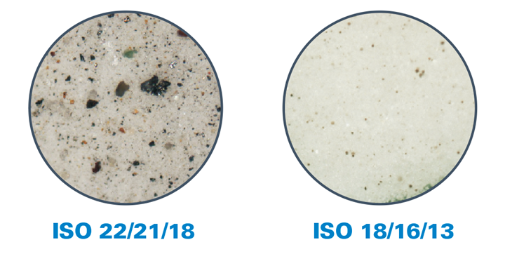
FIG 1. Microphotographs clearly show the difference in contamination level between ISO 18/16/13 oil recommended by Arburg, and ISO 22/21/18, which is more typical of commercially available barrel oil. (Photo: Donaldson Company, Inc.)
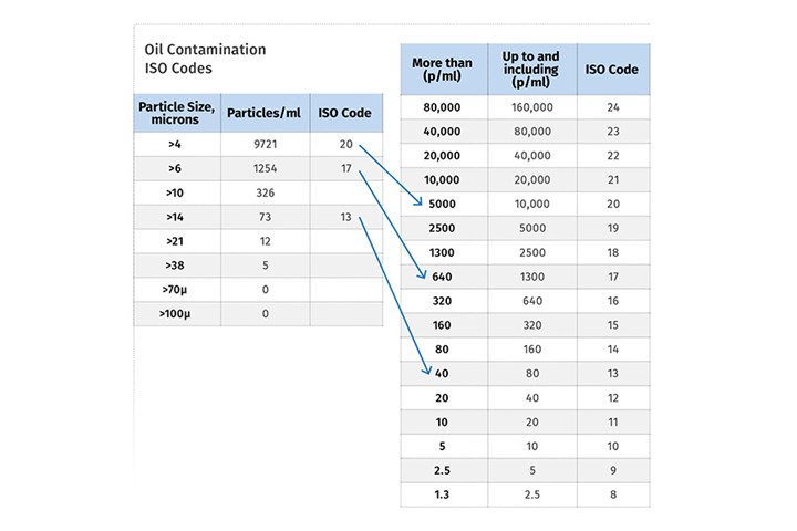
The international ISO 4406:1999 standard is most widely used to achieve a reproducible classification of particulate contamination in hydraulic oils. In this process, the number of particles larger than four, six and 14 microns is determined and assigned to a defined characteristic value or ISO code number. Those three code numbers (for example 20/17/13) together describe the level of contamination of the fluid. The first code number represents the particle count range of all particles greater than 4 microns in size; the second number represents the count range of particles greater than 6 microns; and the third number represents that of all particles greater than 14 microns (see accompanying table).
Any lack of cleanliness in handling components during factory assembly can become a route to oil contamination.
The purity of a hydraulic oil can thus be assessed very quickly and simply by referring to this three-number code. It should be noted that the increase of any of these values by a factor of one represents a doubling of the number of particles (Fig 1).
The table at the left offers hypothetical counts for particles in the >4, >6, and >14 micron size range. The table at the right converts the number of particles of different sizes into an ISO code that defines oil contamination level. In this example, the ISO code for this oil sample would be 20/17/13. (Source: Chevron Lubricants)
How Hydraulic Oil Becomes Contaminated
First of all, a lack of cleanliness in handling components during factory assembly is worthy of mention. This so-called original or initial contamination of the hydraulic system can have a decisive effect on the reliability of an injection molding machine. Naturally, the lower the degree of original contamination, the more wear-free the hydraulic system will be initially. Consequently, oil management always begins with the manufacturer of the hydraulic components and the molding machine.
Prior to assembly, for example, cast parts such as the housing or cylinder covers should be freed of soiling in cleaning machines like the one shown in Fig. 2. Once cleaned, all the components must be kept in closed boxes (Fig. 3) or under protective film until they are installed. A similar procedure applies to the hydraulic pipes and hoses, which are rinsed out and then protected from soiling by means of plugs or caps. Before it leaves the factory, each molding machine should be commissioned using a high-purity hydraulic oil that is regularly monitored and is significantly cleaner than what is normally required.
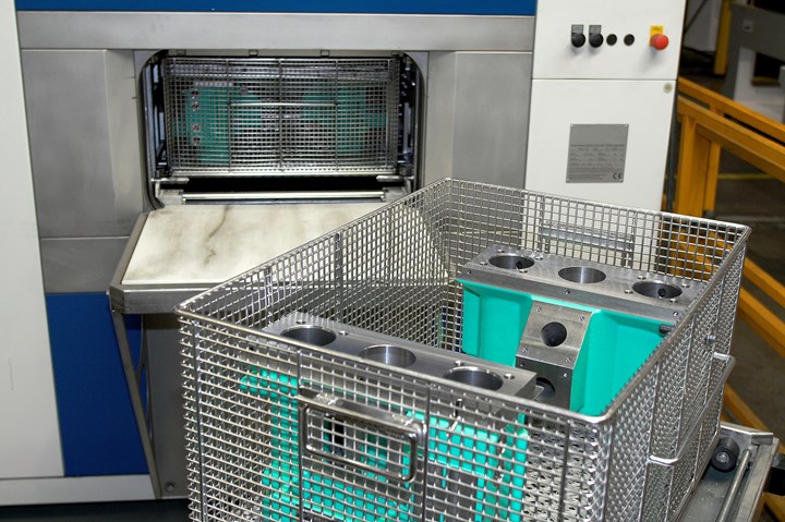
FIG 2 Oil management begins at manufacture of the molding machine and its hydraulic components. Prior to assembly, Arburg cleans cast parts in a machine like this one to remove any soiling deposited during manufacture. (Photo: Arburg)
All these efforts on the part of the machinery manufacturer would be nullified, however, without the molder’s cooperation. Arburg Allrounder machines, for instance, require purity class ISO 18/15/12 and conventional drum oil does not meet this standard. Therefore, the oil tank should always be filled via micro-filter units (Fig. 4). After commissioning, Arburg always evacuates the oil tank completely prior to shipment (Fig. 5).
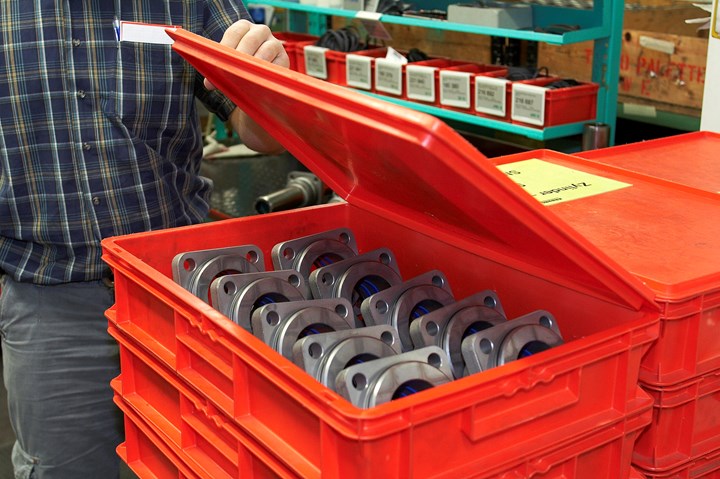
FIG 3 Cleanliness is a priority at Arburg: For example, cleaned components are kept in closed boxes until assembly. (Photo: Arburg)
In addition, hydraulic oils should always be stored in their original container or a cleaned barrel with a closed lid so as to maintain their purity class. If these measures are not observed, contamination of the hydraulic system will automatically occur, and damage or even premature failure of hydraulic components is virtually assured.
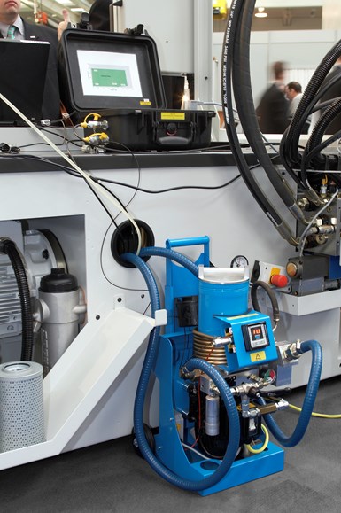
FIG 4 To achieve the necessary level of cleanliness, standard hydraulic oil should undergo microfiltration before being pumped into the molding machine tank. (Photo: Arburg)
The final step in effective oil management is the regular performance of oil-condition analyses. These permit the reliable detection of unusual contamination of the hydraulic oil. If such contamination does occur, molders should check carefully for wear on pumps and seals, for example. Both problems should be fairly obvious, as leaking seals will allow fluid out of the closed system, and pump issues can allow air into the oil, making it look lighter or foamy.
Preventing damage to hydraulic components by oil contamination is not difficult. It merely requires an understanding of how oil becomes contaminated and the discipline to follow the guidelines and procedures described above. By keeping these principles firmly in mind, molders can ensure their equipment continues to operate reliably for many years.
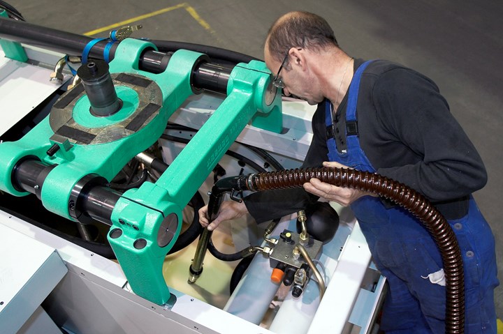
FIG 5 Before shipping any hydraulic molding machine, Arburg vacuum-evacuates the oil tank. (Photo: Arburg)
ABOUT THE AUTHOR: Dietmar Müller, manager of technical services, has worked for Arburg for over 40 years and currently heads the technical service team at Arburg, Inc. in Rocky Hill, Conn. Contact: usa@arburg.com; (860) 667-6500; arburg.com.
Related Content
How to Select the Right Tool Steel for Mold Cavities
With cavity steel or alloy selection there are many variables that can dictate the best option.
Read MoreWhat to Look for in High-Speed Automation for Pipette Production
Automation is a must-have for molders of pipettes. Make sure your supplier provides assurances of throughput and output, manpower utilization, floor space consumption and payback period.
Read MoreProcess Monitoring or Production Monitoring—Why Not Both?
Molders looking to both monitor an injection molding process effectively and manage production can definitely do both with tools available today, but the question is how best to tackle these twin challenges.
Read MoreA Systematic Approach to Process Development
The path to a no-baby-sitting injection molding process is paved with data and can be found by following certain steps.
Read MoreRead Next
Cut Operating Costs—and Headaches with the Right Hydraulic Oil
A big automotive molder found that switching hydraulic oils had a major impact on downtime, maintenance, and energy efficiency.
Read MoreOil Additive Helps Hydraulic Presses Save Energy
Hydraulic oil additive maintains more uniform viscosity over a range of oil temperatures.
Read MoreSwitching Hydraulic Oil Saves Energy & Machine Downtime
Test at leading molder shows a high-viscosity, zinc-free oil improves pump efficiency and runs longer, cleaner, and quieter.
Read More

