Know Your Head Tooling Requirements
The head tooling consists of the mandrel and bushing. Its purpose is to form the parison size needed to make a given part.
In my last column (Making a Part for the First Time? Here’s How to Get Going, March 2011), I wrote about forming the parison and parison layflat. Let’s now delve more deeply into those issues with a discussion on the available options in head tooling for accumulator-head blow molding machines.
The head tooling consists of the mandrel and bushing. Its purpose is to form the parison size needed to make a given part. There are two categories of head tooling: diverge and converge. Diverge is used for larger parison diameters (see Fig. 1), while converge (Fig. 2) makes a range of smaller parisons within the same head. These “rules” aren’t iron-clad, however, as there is a crossover point between the two tooling types. For example, a 20-lb head will have a total range from 2-in. to 14-in. tooling diam. Converge tooling must be used up to about 5.5 to 6 in. diam. and diverge tooling from 6 to 14 in.
Users of diverge tooling usually experience less parison “curtaining”—vertical fold-overs—than those running converge tools. Diverge-type tooling also generates parisons with less swell ratio than converge tools because the plunger is on the outside and the diverter on the inside of the head. However, diverge tools require more force to program, since there is more area for the plastic to push against. This can require more force or larger shoot cylinders, which in turn could create the need for a larger program cylinder to keep the system in balance. Diverge tools also require finer programming of the differential angle between bushing and mandrel (should be in the 2° to 7° range). In this design, the tip is usually inboard of the bushing ring.
Blow molders that use converge tooling often notice more swell (good and bad) on the parison. Less force is required to program the mandrel. In converge tools, the tip extends beyond the ring to prevent parison hang-up.
DETERMINING ANNULUS GAP
Regardless of type, head tools have an annulus gap between the bushing and the mandrel in the land-length area that must be set up for thick or thin wall distributions as the parison is purged from the tooling. Use this as a guide:
Annulus Gap Land Length Wall Thickness
Above 0.100" 1 to 2" Very thick
0.030 to 0.100" ¾ to 1" Moderate
Below 0.030" ¼ to 3/8" Very Thin
At a gap of 0.100 in., the flow pressure of the material will be balanced around the tooling due to the long land length. If the land length is 2 in. with an annulus gap below 0.030 in., the flow pressure would be very excessive during parison push-out. Most likely, you will not be able to control the parison and the desired profile.
The most common angles for the bushing and the mandrel are 30% and 34%, respectively, and it’s easy to predict what might happen if they are manipulated. For example, if you programmed a 20% bushing angle and a 27% mandrel angle, a large movement of the annulus gap would be necessary with very little difference in the gap opening through this range. Many automotive parts require very thin walls—down to 0.025 in. This is difficult to accomplish, and many parts are thus in the 0.040 in. thickness range.
During setup of the gap between the bushing and the mandrel, you will want to set a “zero-position” mechanical die gap of about 0.010 in. This is done by measuring around the entire gap with feeler gauges. There is also a mechanical adjustment on the program rod extension. This prevents the bushing and mandrel from shutting off the gap completely and hitting metal to metal, which will create an offset pressure between the two. Another adjustment once the zero position is accomplished will be to set the electronic setpoint for the annulus gap. This will add another 0.005 in. to the gap opening. These numbers are usually satisfactory as long as there is no drool from the gap.
Beware of potential mechanical restrictions on the top internal area of bushing and mandrel. Poor design could create an interference for parison programming. A protrusion on the upper mandrel area could cause an interference with the bushing while programming. By moving the mandrel down, the protrusion on the head will minimize flow in this area, causing a very thin area on the parison. This area of the mandrel would have to be redesigned.
When using maximum head tooling on an accumulator head you might have to slow down the shot speed. The high pressure and speed of the parison drop causes the mandrel tooling to open with very little holding control. At this point you have lost parison programming control and the part will be out of spec.
As the parison begins to get pushed out, it will experience its largest percentage of diameter swell. That’s because the material has been sitting in the tooling area under pressure waiting to be purged out of the closed tooling. As the parison gets pushed out, the weight of the parison will actually pull it down. This is called drawdown. Hence the bottom of the parison will be larger in diameter than the top section. This could be good or bad depending upon the type of mold that is in the press. You should study the design of the part and determine that the actual orientation is proper.
CORRECTING CURL
Parison curl is caused by uneven distribution of material in the upper accumulator-head area. The pressure drops around the circumference are not equal all the way around the diverter. This often occurs when the majority of the flow comes straight down the extruder inlet side of the material flow area in the head. This can be corrected by adjusting the bushing to be offset by pushing in on the bolts on the heavy-wall side of the parison.
Heater bands are mounted on the accumulator-head body. Many machine builders normally make the heaters line up straight in a vertical line. This looks great, and the actual wiring looks splendid. The trouble is that the design can cause some setup issues. This arrangement leaves two vertical bands on the body of the head that are not being heated, which creates a straight cold area on both sides of the heaters. The best solution is to stagger each horizontal row to overlap the heater above and below it to reduce the cold spots to a minimum. The net result is a more uniform parison wall distribution around the entire body of the head.
Related Content
Understanding Melting in Single-Screw Extruders
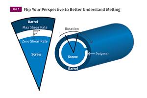
You can better visualize the melting process by “flipping” the observation point so the barrel appears to be turning clockwise around a stationary screw.
Read MoreThe Effects of Stress on Polymers
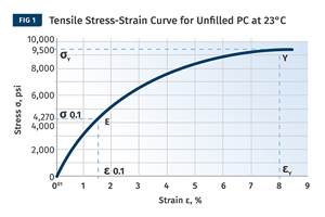
Previously we have discussed the effects of temperature and time on the long-term behavior of polymers. Now let's take a look at stress.
Read MoreBack to Basics on Mold Venting (Part 1)
Here’s what you need to know to improve the quality of your parts and to protect your molds.
Read MoreThree Key Decisions for an Optimal Ejection System
When determining the best ejection option for a tool, molders must consider the ejector’s surface area, location and style.
Read MoreRead Next
Making a Part for the First Time? Here’s How to Get Going
First time parison programming for a new part can be lengthy and tedious. Here's some advice on making the process a bit easier
Read MoreMaking the Circular Economy a Reality
Driven by brand owner demands and new worldwide legislation, the entire supply chain is working toward the shift to circularity, with some evidence the circular economy has already begun.
Read MoreSee Recyclers Close the Loop on Trade Show Production Scrap at NPE2024
A collaboration between show organizer PLASTICS, recycler CPR and size reduction experts WEIMA and Conair recovered and recycled all production scrap at NPE2024.
Read More


