Consider the Cushion When Seeking Shot-to-Shot Consistency
Creating and maintaining a consistent cushion is a key step in achieving shot-to-shot consistency. Learn what cushion is and how it affects part quality.
Cushion values in injection molding ultimately are an indication of a part’s quality, especially its dimensions. A consistent cushion will create consistent part dimensions. The value of the cushion can also be critical in making sure the resin isn’t degraded prior to injection. The cushion value is a result of the settings of the molding parameter inputs and cannot itself be set to a desired value on the molding machine. In this article we will explore what cushion is and how the value of the cushion will affect part quality.
Similar to the graduations on a syringe used at a doctor’s office, Position Zero is when the injection screw is in the forward position. As the screw rotates and picks up the material, it moves back, and its position is measured by increasing numbers. This could be in a linear distance such as inches, millimeters, centimeters, or in volume using cubic centimeters or cubic inches. In this article we will use linear distances with inches as the unit of measurement.
It is important to remember that cushion is not a setting but an output of the molding process.
In Fig. 1, the shot size is set to 3 in. and the transfer position is set to 0.80 in. The screw will start moving to fill the mold from 3.00 in. and will transfer into the compensation or pack-and-hold phase at 0.80 in. During the compensation phase, the screw continues to travel farther for a set time and at a set pressure. The higher these numbers, the farther the distance traveled by the screw. The plastic that remains in front of the screw and does not travel into the mold is called the cushion, and the position the screw reaches is called the cushion value.
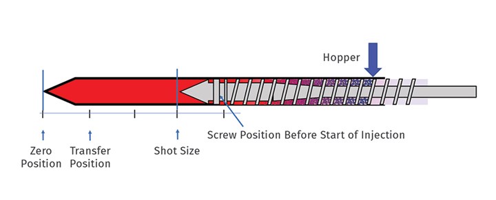
FIG 1 Position Zero is when the screw is in the forward position.
Figure 2 shows the front section of the screw and barrel after the compensation phase. Here the cushion value is 0.15 in. It is important to keep in mind that this is not a setting but an output of the molding process. There must always be cushion present in front of the screw.
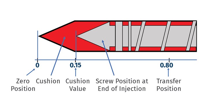
FIG 2 Cushion is found in the front section of the screw and barrel after the compensation phase.
No Cushion, No Pressure, No Packing
We can illustrate this concept (Fig. 3) using a theoretical assembly of two chambers linked via a connector. There is a piston in the top chamber, and a gauge is fitted to the bottom chamber. In Scenario 1, there is fluid in Chamber 1, and therefore a force exerted on the fluid will get transferred through the connector to the fluid in the bottom chamber. This can be confirmed by the increase in pressure shown on the gauge. However, if the top chamber is empty as, shown in Scenario 2, no amount of force applied on the piston will exert any pressure on the fluid in the bottom chamber, and the gauge will always read zero pressure. It is therefore clear that some amount of fluid must be present in the top chamber in order to see any pressure in the bottom chamber.
During the compensation phase of the molding cycle, pressure must be constantly applied on the melt inside the cavities of the mold. This pressure will help to deliver plastic, compensate for shrinkage and pack the cavities out. Similar to the example in Fig. 3, it is the cushion that helps apply this pressure. Lack of cushion will result in short shots and/or underpacked parts. Therefore, a cushion must be present at the end of the compensation phase to mold parts to the desired acceptable quality.
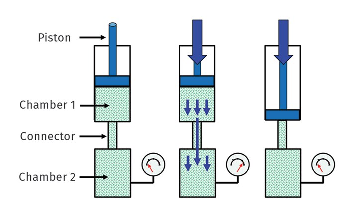
FIG 3 The importance of cushion can be illustrated using a theoretical assembly of two chambers linked via a connector.
Less Is More
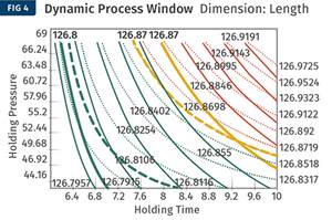
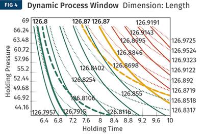
Cushion values must not be too large. Instead, there should be just enough cushion to help apply the desired pressures. There are two reasons to have a small cushion value. First, the plastic melt is compressible like a ball of rubber bands, and a large cushion can consume part of the applied pressure to compress the melt, lowering the pressure inside the cavities. This would be especially important for high-viscosity or highly filled materials, or in processes that are close to being pressure limited. In these cases, a large cushion can cause shot-to-shot variation and lower process capability (Fig. 4).
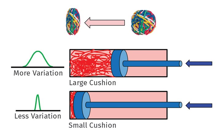
FIG 4 The compressability of resin means a process can have too much cushion.
The second reason is of greater importance. The front zone and the nozzle body almost always have the highest temperature settings compared with the rest of the barrel settings. The higher the temperature, the lower the maximum allowable residence time is for a given plastic. In other words, the plastic in the nozzle area can degrade more quickly than the rest of the plastic in the barrel. This plastic has already built up residence time in the barrel and now it has reached the highest temperature zones of the barrel.
Another way to think about this is to visualize fountain flow or the phenomenon where plastic flows into a mold like water in a fountain—inside out (Fig. 5). Because of this, the plastic that enters the mold first forms molded part’s skin, while the plastic that follows will travel to the end of fill and eventually pack out the part from the inside.
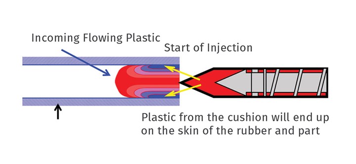
FIG 5 The plastic that enters the mold first—coming from the cushion—forms the skin of the molded part.
Now consider a part with a cold runner. If the cushion values are small, the plastic in the cushion will form the skin of the runner system. If this plastic was degraded or close to being degraded, it wouldn’t matter, since this material ends up in the runner. However, if the cushion is large, then this plastic can end up in the part and cause a failure. It can also lead to cosmetic defects such as splay showing up in the parts. Material degradation in the nozzle area is not common, but it is a possibility in cases of molds with long cycle times using a smaller percentage of the barrel. For this reason, cushion values must be kept small.
To illustrate this, note the following demonstration. It is not recommended that this demonstration be performed, since the results are already shown here. However, in case someone wants to attempt this, extreme care must be exercised at all times. Heat gloves with arm sleeves, safety goggles and face-protection equipment must be worn. Plastic pressures and temperatures are high enough to cause injury. Repeating again: extreme care must be exercised.
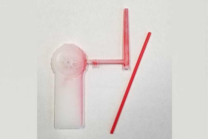
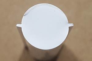
FIG 6 Plastic in the nozzle forms the skin of the runner.
The part was being molded with natural HDPE. At the end of shot, with the screw at the required shot size, the barrel was pulled back. Similar to decompression, the screw was linearly retracted about half an inch to release any melt pressure. With extreme care, a roughly 2-in. long red coffee stirrer was inserted into the nozzle tip. The idea was to use the red color to simulate the degraded plastic present in the nozzle tip. Molding was resumed. Figure 6 shows the result where the red color is mainly present on the skin of the runner with some in the part. This demonstrates that the higher the amount of degraded plastic that is present in the front zones, the greater the chances that the degraded plastic will end up in the part. This again suggests that cushion values should be kept small.
Typically, for screw diameters of 25 to 60 mm, cushion values must be maintained around 0.20 in. or 5 mm. Larger screw diameters should have larger cushions. There is a rule molders use that cushion values should be a certain percentage of the shot size or the screw diameter. Once we understand the concept of the cushion and its significance, we realize there is no basis for those rules and so they should not be used.
A consistent cushion is a sign of consistent amount of plastic being delivered to the cavities, which, of course, is an indication of shot-to-shot consistency, since the volume from the shot size to the cushion is consistent. The cushion must be monitored on every molding machine, and alarm limits must be set to alert personnel in case of any drift from the cushion values. Typical values for tolerances are ±0.05 in. or 2 mm, but these must be set based on the part dimension tolerances, with a design of experiment (DOE) performed in some cases.
ABOUT THE AUTHOR: Suhas Kulkarni is the founder and president of Fimmtech, San Diego, an injection molding service-oriented firm focusing on Scientific Molding. Fimmtech has developed several custom tools that help molders develop robust processes, and its seminars have trained hundreds of individuals. Kulkarni is an author of the best-selling book, Robust Process Development and Scientific Molding, published by Hanser Publications. Contact: (760) 525–9053; suhas@fimmtech.com; fimmtech.com.
Related Content
Optimizing Pack & Hold Times for Hot-Runner & Valve-Gated Molds
Using scientific procedures will help you put an end to all that time-consuming trial and error. Part 1 of 2.
Read MoreFundamentals of Polyethylene – Part 6: PE Performance
Don’t assume you know everything there is to know about PE because it’s been around so long. Here is yet another example of how the performance of PE is influenced by molecular weight and density.
Read MoreInjection Molding: Focus on these Seven Areas to Set a Preventive Maintenance Schedule
Performing fundamental maintenance inspections frequently assures press longevity and process stability. Here’s a checklist to help you stay on top of seven key systems.
Read MoreWhere and How to Vent Injection Molds: Part 3
Questioning several “rules of thumb” about venting injection molds.
Read MoreRead Next
The Cosmetic Process Window: Key to a No-Tweak, Robust Process
Establishing a process with the widest possible cosmetic window can help put your injection molding on cruise control.
Read MoreOptimizing Pack & Hold Times for Hot-Runner & Valve-Gated Molds
Using scientific procedures will help you put an end to all that time-consuming trial and error. Part 1 of 2.
Read MoreProcess Capability and the ‘Hesitation Effect’
Understanding the concepts of pack and hold and applying them during process development is critical for molders to achieve consistent part quality.
Read More
