Evaluating a Corrugator For Small Tube Applications
Tips & Techniques
Here's a review some of the key variables in the technology and how they impact the process.
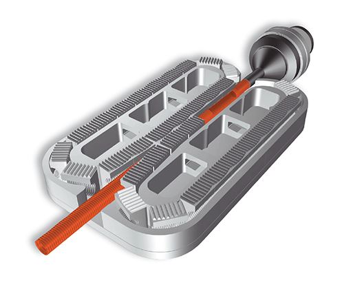
The pipe corrugator, which is a sophisticated puller moving molds past a fixed extrusion point, has been used for decades to make corrugated pipe and many other hollow endless parts with a repeating shape not suitable for standard profile extrusion. Corrugators have also been used experimentally to make continuous hollow close-ended parts, and solid extrusions using a low pressure injection molding technique, but to date there are no known commercial projects in these two specialty areas.
In this article we will review some of the key variables in the technology and how they impact the process. We will discuss evaluating the technology when designing a new product, and how to evaluate a corrugator machine. We will focus primarily on smaller-diameter, single-layer technical tubing with less than 75-mm OD.
When evaluating a technical tube corrugating process, make sure you take the time to understand what the output-limiting factor will be—most likely die pressure, machine cooling limit, or mechanical speed. When making special profile sections, such as cuffs, this short section within the repeating product design might itself be the limiting point and should be evaluated separately for its process requirements and effect on the process line speed. Understanding these factors will help optimize the tooling investment to run a product on a corrugator.
The first thing you’ll need to understand when considering a corrugator for making parts will be the part diameter and how this relates to the mold block length and resulting die length. The higher the die-length to diameter ratio becomes, the more likely that backpressure will be a limiting factor in the process output for the material you are trying to run. Depending on the die’s diameter and length, you’ll also have to consider the wall thickness of the outer die and its ability to withstand the operating pressure without rupture.
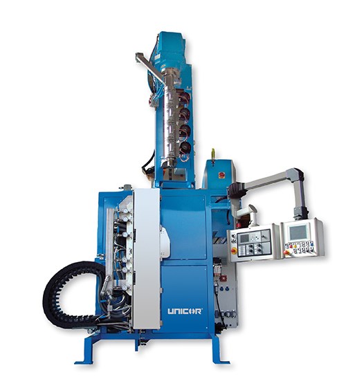
Looking at the options to minimize die length, the first is to locate the die external to the forming channel. There are two methods to accomplish this, both requiring the use of a vacuum-forming corrugator. The first way to operate with the die external to the corrugator forming channel is to orient the process vertically, like an extrusion blow molding machine. In this case you’ll drop a continuous parison into the forming channel of the corrugator and draw the air out between the parison and mold surface using a vacuum pump and porting within the molds. Vertically oriented corrugators have been used primarily for making very small-diameter parts—e.g., 1/8-in. (3-mm) ID—in which the die cannot be practically made to extend within the corrugator.
A second method to reduce the die length and keep it to the outside of the corrugator is to use an internal material to support the parison as it is being drawn into the corrugator. Typically this material will be moving at an extrusion speed similar to that of the parison being formed in the corrugator. This is the typical process used for making pipe where a smooth pipe is run through a crosshead die external to the corrugators; the parison is extruded over this center pipe and subsequently formed into a corrugated tube within the corrugator vacuum forming chamber. This technique is also used for wire insertion within a corrugated pipe but is very sensitive to the melt strength of the material being used.
In most cases, the die is going to extend into the corrugators forming channel and will operate in a horizontal orientation. In these cases, pay close attention to minimizing the die length, especially when using high-viscosity materials such as rigid PVC, CPVC, and PP. The way to minimize die length is to look for a corrugator with the shortest possible mold length and tightest mold inlet radius to the corrugator forming channel. As a rule, in the small-diameter technical product area—under 4 in.(100 mm) OD—try to avoid die-length to die-diameter ratios greater than 4:1 to help minimize backpressure and maximize output.
Another effect on backpressure when operating a vacuum corrugator will be the cooling effect from the vacuum-forming system drawing air into the corrugator middle channel. This cooling effect can be troublesome on small dies using very temperature-sensitive crystalline materials such as nylons and fluoropolymers, which can freeze quickly in the die. This cooling effect can also cause melt fracture of the material as it leaves the die, giving the external surface the typical patterns associated with the slip/stick action.
Cures for the vacuum cooling effect are numerous and include insulating the die, directing preheated air over the die, adding resistance heating to the die, and sometimes choosing not to use vacuum forming and reverting to traditional blow molding, which is often the case when running small-diameter nylon tubes.
DETERMINING LINE SPEED
Once the review of the material is complete and a decision on the style of die and resulting corrugator orientation and mold length is determined, the next question becomes how fast the line can be run. As with all plastic processes, cooling time governs the output; in the case of a pipe corrugator it requires determining the acceptable temperature at which the product can leave the machine and how many seconds of contact time we need to achieve this at the desired line speed.
Assume it takes 6 sec to cool the profile to a temperature stable enough to release it from the molds. Knowing this, if you want the product to run at 50 ft/min, you should be running a corrugator with a forming channel of 5 ft. If we want to run the same product at 100 ft/min, you’ll need a corrugator with a forming channel of 10 ft.
In the product range of 1/8 to 3-in. OD, typical corrugator designs have a range of forming channel lengths of 3 to 8 ft, though specialty machines have been built for applications as long as 40 ft. Many corrugators come in a variable-length design, so that the forming channel can be adjusted for the optimum combination of output and capital investment. The longer the corrugator, the more molds you need to buy, hence a larger investment.
The next consideration is the temperature at which you can run the mold blocks. Obviously the colder the molds, the higher the delta T and the shorter the contact time needs to be to release the product from the machine. In corrugating, this relationship also has to take into consideration part finish and the available pressure to hold the product tight to the mold surface and achieve a smooth, acceptable finish. As vacuum corrugating works in a much lower forming-pressure range, typically less than 11.6 psi (0.8 bar), the molds normally will need to be quite warm to find the balance between optimum cooling and optimum finish. A typical mold temperature for polyolefin materials would be in the 140 F range, which is quite warm compared with blow molding and injection molding.
The other consideration in cooling becomes the method of cooling the machine itself. There are three typical systems: air cooled using plant air; air cooled through liquid-cooled heat exchangers; and direct water cooled. All three systems work effectively to maintain the mold blocks within an acceptable operating range, which is important to manage the shrinkage rate of the tubes. From general experience, the molds should have a target range of temperature variance of about 10° F, but this is very dependent on the product’s dimensional tolerances. More consistent mold temperatures result in more consistent shrinkage rates.
Corrugators using plant air for cooling are the simplest to operate and least expensive. Areas where these machines are well suited are air-conditioned plants, and northern locations where the daily plant temperature stays below 90 F. In a cool operating environment, the cooling is relatively free; and with a low variance in plant temperature the mold-block temperature can be controlled within an acceptable range.
Air-cooled corrugators with water-cooled heat exchangers have been built for many years, but recent innovations have improved their efficiency. The more innovative designs in this area use much larger heat-exchanger surface area, in combination with sophisticated air direction, air recycling, and variable-speed fan motors to better control the mold temperature. These machines are well suited for plants with high variability in day-to-evening temperatures and can operate in the high-temperature southern plants typical of the U.S. and Mexico.
Water-cooled corrugators have also been available for decades; in the 1/8- to 3-in. diam. range, they typically consist of a water-jacketed system using contact and radiant heat transfer. These machines are well known for efficient cooling and tight temperature control in plants with a wide range of temperatures. These machines also tend to be very quiet, since there are no fans needed. One thing to watch in plants where there is high humidity is management of condensation on the external housing of the machine and supply pipes.
The final consideration in cooling becomes the selection of mold material. Both aluminum and steel are common, as are aluminum master molds with steel inserts. The decision of which to use can only be made after a thorough discussion with your machine supplier. Aluminum conducts heat faster than steel, but many polymers give the heat up slower than either material will conduct it away. Steel molds are known to outlast aluminum in high-use applications, but also come with a higher cost of manufacturing. When the mold blocks are sliding in a housing, steel is the material of choice, but if the corrugator is using a carrier technology then aluminum molds work well.
Cooling on corrugators has many facets, and to make the proper choice make sure you understand the specifications your product has to meet. If it’s an end use where dimensional tolerance has no impact on the parts, then mold-temperature variance will have little impact on the process. But if the part requires high dimensional accuracy then select a cooling technology that can be tightly controlled and has minor variance.
The mechanical speed of the corrugator is the final area of consideration. It is seldom a problem that a corrugator is not able to run fast enough, but there are a number of areas you should review as you look at the mechanical drive train of the machine.
Look at the motor/gearbox combination and ensure it is properly geared for the speed ranges you are planning to run. If you have a lower-speed application with a heavy pipe weight and are using traditional blow molding (such as for an electrical non-metallic tubing product), the motor and gearbox will be quite different from what is appropriate for a lightweight, high-speed PE tubing made with a vacuum corrugator. These differences will have a lot to do with your long-term energy bill, so doing a complete review of the range of speeds the machine will run, and verifying that the machine manufacturer is supplying the optimum drive train, is a worth the effort.
As corrugators become longer, thermal expansion of the mold set increases, which can cause a gap between the molds when the machine is in its cold startup condition. This is a manageable situation but can mean that startups are prone to mistakes and higher maintenance on the machine. A common remedy in newer corrugator technologies is to add a return drive on the corrugator end, with the result of halving the mold thermal expansion.
Related Content
Understanding Melting in Single-Screw Extruders
You can better visualize the melting process by “flipping” the observation point so the barrel appears to be turning clockwise around a stationary screw.
Read MoreThe Importance of Barrel Heat and Melt Temperature
Barrel temperature may impact melting in the case of very small extruders running very slowly. Otherwise, melting is mainly the result of shear heating of the polymer.
Read MoreWhat to Know About Your Materials When Choosing a Feeder
Feeder performance is crucial to operating extrusion and compounding lines. And consistent, reliable feeding depends in large part on selecting a feeder compatible with the materials and additives you intend to process. Follow these tips to analyze your feeder requirements.
Read MoreHow Screw Design Can Boost Output of Single-Screw Extruders
Optimizing screw design for a lower discharge temperature has been shown to significantly increase output rate.
Read MoreRead Next
Lead the Conversation, Change the Conversation
Coverage of single-use plastics can be both misleading and demoralizing. Here are 10 tips for changing the perception of the plastics industry at your company and in your community.
Read MoreFor PLASTICS' CEO Seaholm, NPE to Shine Light on Sustainability Successes
With advocacy, communication and sustainability as three main pillars, Seaholm leads a trade association to NPE that ‘is more active today than we have ever been.’
Read More
