Fix Thickness Variations in Extruded Sheet
Non-uniform thickness in extruded sheet is a serious problem.
Non-uniform thickness in extruded sheet is a serious problem. In the case of thin sheet for thermoforming, uniform gauge is critical to achieving proper wall thickness in formed parts and to preventing optical distortion, both serious quality issues for packaging. With heavy sheet, gauge variation brings the added problem of warpage—you often have to reheat the sheet on rollers to get it flat.
Gauge problems in the web can be in the machine direction (MD) or transverse direction (TD) and have a wide variety of causes related to equipment, material, and process. The traditional approach to reducing thickness variations is to add a scanning gauge control system. While beneficial, a better approach is first to address the issues causing the variations. If this can be accomplished, then the gauging system won't have to work as hard and can be used to fine-tune the remaining small fluctuations.
Equipment-related causes
Sheet thickness variations can come from improper screw and/or die design, improper temperature profile, and worn extruder barrels and/or screws. Operators can tell from maintenance records if they have a worn screw or barrel, but they may not recognize it as the source of gauge variations. Screw-induced thickness variations, both MD and TD, are caused by surging and are easy to spot because they're repetitive. A melt pump can help remove variations induced by poor screw design or by wear.
An improper barrel-temperature profile can also cause surging, but a melt pump won't solve this problem, which will be reflected in viscosity variations and thus uneven gauge in both MD and TD. The barrel temperature profile must match the melt characteristics of the resin with the screw design.
Long flow channels in a sheet die are designed for specific operating conditions. If the conditions for running that polymer are not matched to the die design, uneven product can result.
Material-related causes
Gauge problems can result from inconsistent melt temperature going into the feedblock and die and inconsistent feeding and blending. Keeping a consistent temperature in the melt stream is the most critical factor in maintaining sheet dimensions. Melt temperature directly affects melt viscosity. Even small variations in viscosity will change the flow distribution in the die and thus alter the sheet profile. Here, again, an improperly set barrel-temperature profile is apt to be at fault.
Variation in material composition can cause melt temperature and/or viscosity variations. When running blended materials, inconsistent blend ratios may be causing the problem. It makes sense to check that the blender is properly set and operating correctly.
Process-related causes
Inadequate speed regulation, operator-induced variations, and changes in the plant environment can also influence sheet gauge variations. Screw-speed variations directly influence MD thickness uniformity. An extruder can amplify any speed error in the drive system. So even small speed variations can cause significant MD dimensional variations. Speed variation also affects flow distribution, thus changing the TD profile as well. Using modern digital drives with encoder feedback will eliminate speed-induced gauge variations.
Operators' tweaking of process parameters can upset gauge control. What's more, operators tend to want to run the lines their own way. They should not be given a free hand to do so. Operator-induced variations can be reduced by adding total line control, which limits the range of adjustment the operator is authorized to make. Total line control also reduces the start-up time required to arrive on specification. It takes advantage of the fact that the control system knows the entire process and can do a better job than individual discrete controllers or traditional multi-zone controllers that aren't coordinated.
Changes in plant environment—such as a draft from an open door or a fan—can also hurt sheet dimensions. Seasonal changes in temperature and humidity frequently have an adverse influence on web thickness. Outdoor temperatures can affect the cooling-water temperature in the chill rolls. Indoor temperature and drafts can change the cooling rate of the sheet. Thin-gauge sheet is particularly susceptible to changes in ambient airflow.
Even closed-loop profile control can struggle to hold sheet gauge when ambient factors aren't consistent. However, auto mapping, explained below, is a control strategy that helps compensate for environmental variables.
What controls can do
A significant percentage of sheet processors have gauge-control systems. Probably two-thirds rely on manual adjustment based on a measurement system, and one-third have automatic adjustment.
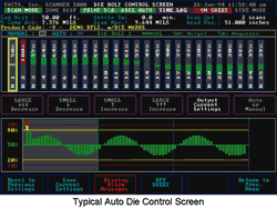
Scanning profile measurement can be tied in with a control system to control average MD thickness by adjusting the extruder (or melt pump) speed or the chill-roll takeoff speed. TD gauge is controlled by adjusting die bolts. However, profile measurement and control systems are by nature slow to correct the TD profile.
Traditional control systems are frequently a collection of independent control loops that correct only deviations in each loop's respective control parameter. Advanced control systems coordinate the entire process and incorporate "feed-forward," or anticipatory, functions to minimize negative interactions between these loops.
A good example of "feed-forward" control is the immediate adjustment of one or more barrel-temperature loops after a speed change. Feed-forward is based on knowledge of historical process events following speed changes. Rather than waiting for the temperature to deviate and for the loop to respond to a temperature error, this technique can significantly reduce the upset to sensitive temperature-control zones.
In many applications, advanced control loops can manipulate the primary control loops to maintain a secondary parameter. An example is automatic adjustment of barrel temperatures over a limited range to hold a constant final melt temperature.
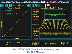
An auto profile control system adjusts the die bolts by relying on an internal software "map" that identifies which portions of the sheet downstream are controlled by which die bolt. Think of it as stripes of sheet coming out of each die-bolt location, but the stripes may not be straight and parallel. Because the sheet stretches and shrinks according to the rate of cooling by the chill rolls and ambient air currents, die-bolt mapping can be quite complex. The auto mapping function tracks the results of die-bolt corrections and then automatically adjusts the internal map of the die bolt stripes. It can't track rapidly changing environmental conditions, but it can provide clues to analyze cause and effect later.
Operators should be provided with the necessary visualization tools to properly manage the process. Since the operator is the "front line" in identifying the source of gauge variations, operators should have a display of trend charts of all process parameters, as well as TD profile plots. Ultimately, most skilled operators can get a line to produce sheet that's flat and in spec, with or without automated controls. But the more automation you have, the less time an operator will spend chasing variations.
Thomas W. ("Tim") Fisher III worked in the engineering lab for Firestone Tire & Rubber Co. in Akron, Ohio, for over a decade before starting FACTS Inc. in Cuyahoga Falls, Ohio, in 1983. It provides process-control solutions for mixing, extrusion, and calendering. The author can be reached at (330) 928-2332 or e-mail: tfisher@facts-inc.com.
Related Content
Medical Tubing: Use Simulation to Troubleshoot, Optimize Processing & Dies
Extrusion simulations can be useful in anticipating issues and running “what-if” scenarios to size extruders and design dies for extrusion projects. It should be used at early stages of any project to avoid trial and error and remaking tooling.
Read MoreUnderstanding Melting in Single-Screw Extruders
You can better visualize the melting process by “flipping” the observation point so the barrel appears to be turning clockwise around a stationary screw.
Read MoreRoll Cooling: Understand the Three Heat-Transfer Processes
Designing cooling rolls is complex, tedious and requires a lot of inputs. Getting it wrong may have a dramatic impact on productivity.
Read MoreHow Polymer Melts in Single-Screw Extruders
Understanding how polymer melts in a single-screw extruder could help you optimize your screw design to eliminate defect-causing solid polymer fragments.
Read MoreRead Next
See Recyclers Close the Loop on Trade Show Production Scrap at NPE2024
A collaboration between show organizer PLASTICS, recycler CPR and size reduction experts WEIMA and Conair recovered and recycled all production scrap at NPE2024.
Read MoreBeyond Prototypes: 8 Ways the Plastics Industry Is Using 3D Printing
Plastics processors are finding applications for 3D printing around the plant and across the supply chain. Here are 8 examples to look for at NPE2024.
Read MoreFor PLASTICS' CEO Seaholm, NPE to Shine Light on Sustainability Successes
With advocacy, communication and sustainability as three main pillars, Seaholm leads a trade association to NPE that ‘is more active today than we have ever been.’
Read More


