How Sprue Pullers Help Prevent Molding Issues: Part 2
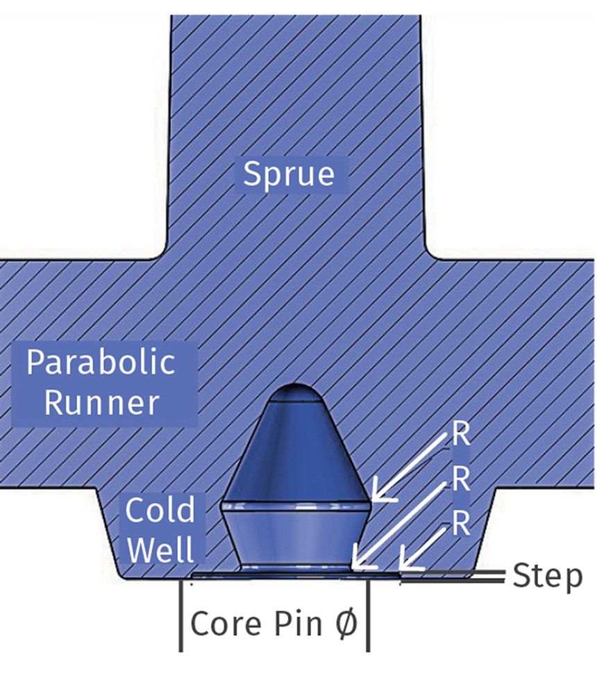
A vital secondary function of sprue pullers is to act as a cold well to trap solidified material left in the machine-nozzle tip.
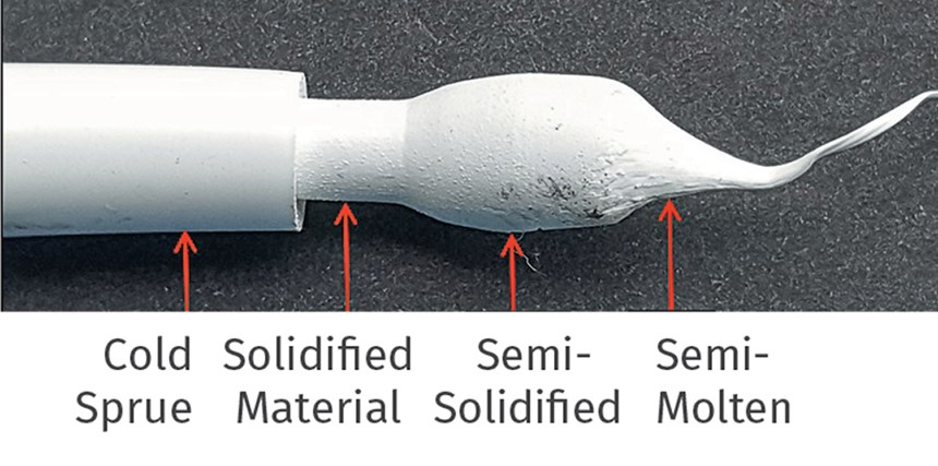
At the start of each molding cycle, there is a small amount of solidified or semi-solidified material in the machine nozzle tip. This solidification is a result of heat being sucked out of the nozzle tip due to surface contact with the cold sprue bushing. The amount of solidified material depends on many factors. They include type of machine-nozzle tip, its orifice size, and the material being molded.
The photo shows molded sprues with and without solidified material attached to their tips. These sprues were made just minutes apart, proving that the size of the solidifed material can vary from shot to shot. The solidified or semi-solidified material, which is missing from the tip of the sprues, is still sitting in the machine nozzle tip, waiting to be injected into the mold on the next shot. If it is fully solidified, it is called a cold slug.
Cold slugs typically cause a spike in the initial injection pressure as the screw tries to push this solid mass out of the nozzle tip. Here’s where the sprue puller comes in: It must also function as a cold well to trap and retain the solidified or semi-solidified material in the machine-nozzle tip. The term “cold well” is usually thought of as an extension of a runner beyond the intersection of another runner, also referred to as an overflow. Regardless of the name, their function is identical: to prevent solidified or semi-solidified material from entering the cavity.
At the Society of Plastics Engineers ANTEC 2002, Patrick Auell and Brian Martonic, both from The Behrend College at Pennsylvania State University, presented a paper that proved that a completely solidified mass located in front of a melt channel will remain in the front of the material flow while being pushed by the material behind it. It will not re-melt before reaching the critical gate location. Nor will it be deposited onto the side walls of the melt channel due to “fountain flow”—the typical method in which thermoplastic material flows.
The authors also proved that a sprue puller/cold well directly opposite the sprue bushing is extremely effective at catching and retaining this solidified material. If the sprue puller does not catch and retain the material, a flow imbalance to the other cavities can occur. In a worst-case scenario, the material will completely block a gate. Therefore, the sprue puller is the single most important and effective cold well in the melt-delivery system. While many molders have always assumed this is exactly what happens, I applaud these two gentlemen for taking us one step closer to validating the phenomenon.
Get more insights on tooling from our expert authors: Know How Tooling
The material in the machine-nozzle tip does not transition from the fully solidified state immediately to a fully molten state. There is a zone of semi-solidified material between the two. This semi-solidified material can either be very small, or it can be very large. It can cause a flow issue, or it can be completely harmless. There is no way to know for sure, and it varies from mold to mold.
Why is this important? Because the volume of the sprue puller should have a direct correlation to the amount of solidified and semi-solidified material in the machine nozzle tip. Ideally, you want the sprue puller to catch and retain all the material that could create an aesthetic or physical issue in the part. The diameter of the sprue puller should have nothing to do with the diameter of the primary runner, nor the diameter of the sprue at the parting line. The diameter and the depth of the sprue puller should be based on the machine-nozzle tip’s orifice size and type. Keep in mind that the goal is not to make the sprue puller too large, nor too small. Both can have detrimental consequences. Too small a sprue puller may not trap all the solidified and semi-solidified material. Too large a sprue puller may not solidify fast enough to keep pace with the desired cycle time. I like to start off with the sprue-puller diameter and depth at 1-1.5 times the diameter of the sprue-bushing orifice. That usually takes care of the smaller solidified material. When sampling the mold for the first time, look to see if some of the sprues have large semi-solidified slugs attached, and if others have small or no slugs attached at all. In a case like this, make the sprue puller deeper to increase its volume. Don’t make it wider. (Note: When designing the mold, make sure to increase the bearing length of the sprue-puller ejector pin, in case the pin needs to be shortened to increase the puller’s volume.
Sprue pullers are also required in most two-plate molds that use hot sprue bushings or hot-runner nozzles—unless the hot-runner nozzle is a valve-gate type. These heated components also have solidified and semi-solidified material that needs to be captured before entering the cavity. The required volume of these sprue pullers is usually much less, because nozzle-tip orifices are usually much smaller than standard cold-runner molds.
“Sprue-gate”-style hot nozzle tips are typically used when gating into a cold runner. They have a small cold-sprue portion, which is usually very short—less than 1 in., but it still should have a puller to remove it. The puller design should have the same basic features as I discussed last month, but the amount of undercut can be much smaller because the force holding the sprue in place is much lower.
Sometimes this type of nozzle tip is gated directly into a part, particularly in single-cavity molds. This is the same condition as in a cold runner mold where the sprue bushing abuts the molded part. In both cases, the part acts as the sprue puller. But they both should still have a means to capture solidified and semi-solidified material.
HOT SPRUE GATE WITH SPRUE PULLER
“Point-gate”-style hot-nozzle tips do not have a cold-sprue portion. But they do have a small amount of solidified or semi-solidified material that must be captured. This type of nozzle tip is typically used when direct gating into a part. If possible, add some type of cold well on the top of the core directly opposite the nozzle orifice. Many such cold wells look and act like a “dispersion disc,” which reduces the amount of shear caused by the hot melt blasting against the top of the core during injection. If you’re not sure what a dispersion disc is, look for the small spherical bump underneath almost any water-bottle cap.
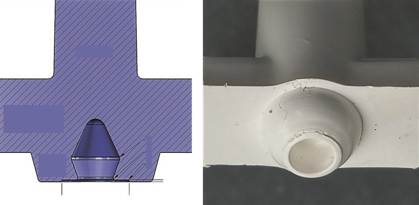
Now let’s discuss a few odds and ends. The first is how to handle a stripper-plate mold. Obviously, this type of ejection method still requires a means to pull the sprue out of the bushing and a means to capture and retain any solidified or semi-solidified material. The images to the left shows one such design. A truncated cone or spherical well captures the material, and the lollipop-shaped sucker pin in its center creates the force necessary to pull the sprue out of the bushing. When the stripper plate advances, the sucker pin is withdrawn from the well and gravity pulls it out of the stripper plate. In cases like this, a long cold sprue is beneficial, because it shifts the center of gravity. It helps the runner “roll” out of the stripper plate, because it will be prevented from sliding vertically down the parting line.
But there is one downside to any lollipop-shaped pin design. The undercut will wear over time, especially if the pin is made of beryllium copper, and must be monitored as to its effectiveness.
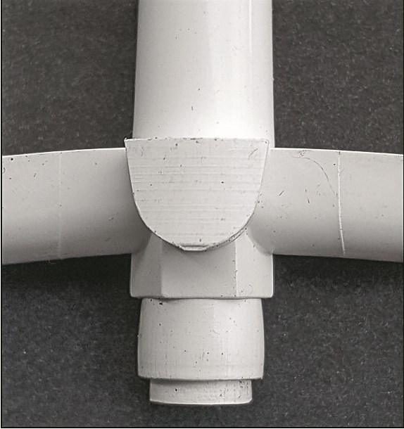
If you have a family mold or need a runner turn-off (RTO) for some reason, there is no reason you can’t EDM a hex into the top of a recessed sprue puller. Just remember to prevent the RTO from rotating by adding a dowel pin, screw, ball detent, or some other retention method.
As I mentioned in last month’s column, if the diameter of the sprue puller is large, the cycle time of the mold is relatively short, and the amount of cooling near the puller is rather poor, the structural integrity of the puller is not going to be very good.
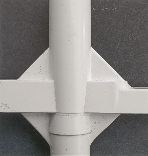
Instead of extending the cycle time to compensate for these conditions, you can try adding gussets connecting the sprue puller to the runner. Adding gussets to any area of a runner will prevent the runner from rotating during ejection. This is usually advantageous, especially with robotic extraction, but on rare occasions it could be a disadvantage as well.
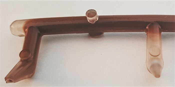
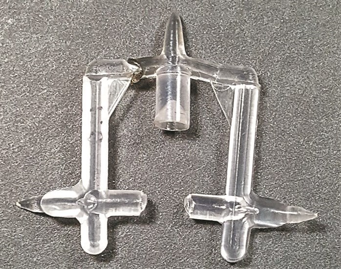
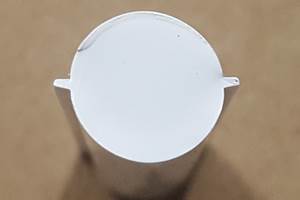
If you are gating into the split line of opposing cams, you may not need the sprue-pulling function of a sprue puller, but you will still need the cold-well function. The photo on the top left of this page shows just such a runner and sprue puller. Note the tapered ejector pin on the underside of the sprue puller.
This prevents the runner from sticking in one side of the cam or the other. It also allows the runner to rotate, which is necessary in this case to prevent the sub-gates from breaking off in the cam face.
One of the most effective ways to reduce cycle time is to core out the sprue puller.
The last subject I want to discuss is how to reduce your cycle time. The sprue puller must solidify enough to perform its function when the parts are ready to be ejected—not when the sprue puller is ready to be ejected. If it isn’t, the cycle time has to be needlessly extended, which means your part cost just went up and your machine availability just went down.
Due to the insulating properties of thermoplastics, if you double the thickness of a part, it will take more than double the amount of time to solidify. That’s because the solidification rate of thermoplastics is non-linear. This is why a sprue puller often is the cause of an extended cycle time.
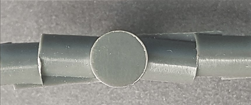
One of the most effective ways to reduce cycle time is to core out the sprue puller. I have seen several sprue pullers that were cored out by the puller’s ejector pin. This is not a good idea, especially for reverse-tapered sprue pullers. Even if the ejector pin is tapered, most of the time a second ejector pulse is required to dislodge the puller from the pin. But more importantly, the extended ejector pin reduces the wall thickness between the undercut and the pin. During ejection, the undercut can’t compress nearly as much as it could if it were solid.
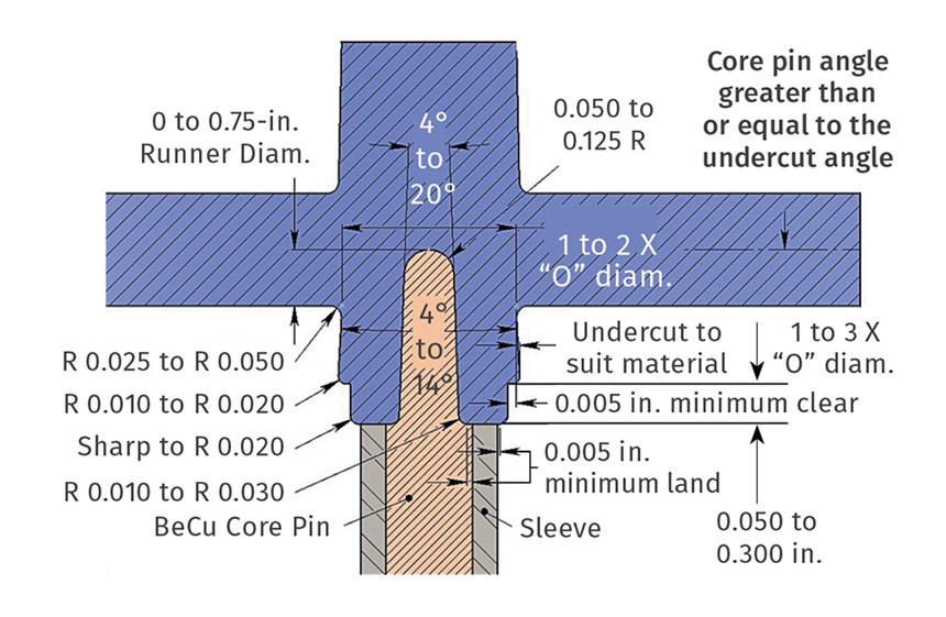
A better way to core out the sprue puller is to use a stationary core pin and eject the puller with a sleeve.
This usually results in tears and flaking. A better way to core out the sprue puller is to use a stationary core pin and eject the puller with a sleeve. I recommend making the core pin out of beryllium copper to increase the cooling rate. As long as the angle of the tapered core pin is greater than or equal to the angle of the undercut on the puller, when the sleeve advances forward the undercut is allowed to compress inward because the core pin is no longer in the way.
While coring out a sprue puller is extremely effective, that doesn’t mean cooling the puller isn’t important as well. Water channels should still be placed strategically nearby. Putting the sprue puller in a water-cooled bushing may be a bit of overkill, or it may be just what the doctor ordered. Ideally, the water near the sprue puller should be on a separate circuit. A molder may run the cavities and cores at, say, 75 F, but would love the flexibility to use colder water on the sprue puller, so as not to have to extend the cycle time.
Cooling is very important with molds having cycle times of 10 sec or less, and with molds requiring multiple ejector pulses. Why? Because ejector pins and sleeves tend to get hotter in molds with fast cycles and multiple pulses. When metal gets hot it expands. Factor in a nice coating of gooey gas residue and the next sound you might hear is a high-pitched screech from galling steel, or perhaps a thud from a pin that just collapsed behind the B-plate. It always amazes me to see how much attention is given to cooling the part, but cooling the thickest masses of plastic in the mold, such as the sprue, the runner, and the sprue puller are hardly given any attention at all.
If you are not sure whether any of these design improvements are worth the extra cost to incorporate them, there is a very simple way to find out. Multiply your molding machine rate in dollars per second (with an operator) by the number of shots per year, times the number of expected seconds saved. If that doesn’t sell you on spending a little more on improving your mold design, take a look at your mold repair costs for the past year. You will probably see many of them could have been prolonged or avoided with a slightly better design.
ABOUT THE AUTHOR: Jim Fattori is a third-generation injection molder with more than 40 years of molding experience. He is the founder of Injection Mold Consulting LLC, and is also a project engineer for a large, multi-plant molder in New Jersey. Contact jim@injectionmoldconsulting.com; injectionmoldconsulting.com.
Related Content
Where and How to Vent Injection Molds: Part 3
Questioning several “rules of thumb” about venting injection molds.
Read MoreHow to Achieve Simulation Success, Part 1: Model Accuracy and Mesh Decisions
Molding simulation software is a powerful tool, but what you get out of it depends very much on your initial inputs. Follow these tips to create the most successful simulation possible.
Read MoreSystem Offers 'Lights Out' Mold-Channel Cleaning & Diagnostics
New system automatically cleans mold-cooling lines—including conformal channels—removing rust and calcium, among other deposits, while simultaneously testing for leaks, measuring flow rate and applying rust inhibitor.
Read MoreWhy Shoulder Bolts Are Too Important to Ignore (Part 2)
Follow these tips and tricks for a better design.
Read MoreRead Next
Lead the Conversation, Change the Conversation
Coverage of single-use plastics can be both misleading and demoralizing. Here are 10 tips for changing the perception of the plastics industry at your company and in your community.
Read MoreBeyond Prototypes: 8 Ways the Plastics Industry Is Using 3D Printing
Plastics processors are finding applications for 3D printing around the plant and across the supply chain. Here are 8 examples to look for at NPE2024.
Read More

