How to Fix Vent-Flow Problems
Putting one or two vents between the feed throat and die is a good way to remove moisture, trapped air, and other volatiles from melted plastic as it moves through an extruder.
Putting one or two vents between the feed throat and die is a good way to remove moisture, trapped air, and other volatiles from melted plastic as it moves through an extruder. But openings in the barrel can also make for problems. One of the most common difficulties is plastic flowing out of the vent. Even a small amount of vent flow hurts removal of volatiles, so product quality suffers. A lot of vent flow can plug the vent and force a shutdown of the extruder.
Two things cause vent flow: Improper screw design causes melt to back up under the vent. Or, a poor vent design “scrapes” passing melt into the port. The first step is to look into the vent port to see if melt is backing up in the screw. In most vented extruders, you can actually see the screw turn and the melt move forward. (Be sure to wear safety glasses!) Melt forms a rolling bank against the pushing flank of the screw flights, which should fill no more than 50% of the channel. If the screw is more than 50% full, screw design is probably causing the vent flow. If the screw is less than 50% full, then the screw is working correctly and the vent port and/or insert or diverter is probably causing the vent flow.
Fixing screw problems
A vented extruder requires a special screw geometry with multiple stages to keep the melt under the vent ports at zero pressure so it doesn’t flow out. An extruder with one vent needs a two-stage screw; an extruder with two vents needs a three-stage screw. Each stage has its own zero-pressure section followed by compression and metering/pumping sections. The first stage starts with a zero-pressure feed section. Subsequent stages start with a zero-pressure extraction section, where the vent is located.
Two issues are important in screw design for a vented extruder. First, plastic has to be completely melted when it reaches the extraction section in order to permit volatiles to escape. Second, conveying capacity in the second stage must be greater than that in the first stage, so that the screw channel at the beginning of the second stage is starved. This keeps zero pressure under the vent.
Melt backs up in the extruder when the reverse occurs—i.e., when the first stage pumps more plastic than the second can handle. To solve the problem, you have to either reduce pumping capacity in the first stage or increase pumping capacity in the second stage.
A quicker fix
The fastest and easiest answer is to change process conditions rather than rework the screw. For example, Reducing temperatures increases friction and viscous stress along the barrel or screw, while raising temperatures reduces it. Increasing friction or viscosity along the barrel increases conveying, while increasing friction or viscosity along the screw surface reduces conveying.
The conveying capacity of the first stage can be reduced by several means:
- Increasing barrel temperatures in zones 2 and 3.
- Adjusting barrel temperature, usually downward, at the beginning of the first stage.
- Cooling the screw in the first stage.
- Starve-feeding the extruder.
- Adjusting the temperature of the feed housing (by trial and error).
Alternatively, to increase the conveying capacity of the second stage one could try these steps:
- Reduce barrel temperatures in the second stage.
- Increase screw temperature in the second stage.
- Increase die temperature.
- Open the die gap or die restriction.
- Change a dirty screen pack.
- Reduce the number of screens in a screen pack.
- Use a screen with larger holes.
It may not be possible to determine ahead of time whether increasing or decreasing the temperature of the initial feed zone will give better results. Both should be tried, and the results carefully monitored.
If the problem can’t be solved by changes in operating conditions, more expensive solutions are a new screw design, a less restrictive die, longer screw and barrel, starve feeding, or installing a gear pump between the extruder and die. The last solution—a gear pump—would probably solve the vent-flow problem, but it costs substantially more than a new screw.
Fixing a poor vent port
If the screw channel is only partially filled under the vent port, and there is still vent flow, the vent itself is the likely culprit. There is little published information about diverter designs, so few people know the difference between a good and bad one.
The vent opening should be wider than the rolling bank of melt to make sure the opening doesn’t get closed off by the melt. At the same time, the vent opening should not be too big, in order to minimize melt exposure time and swelling of the rolling bank.
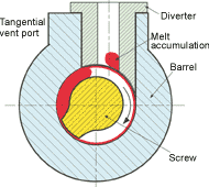
In normal operation, when the screw channel is half full, only the empty half is at zero pressure. Positive pressure still develops in the rolling bank. The pressure may be 30 to 50 psi or more in the rolling bank, enough to make the bank expand under the vent opening. So the vent port has to be designed to handle this normal visco-elastic expansion (see Fig. 1). Otherwise, part of the rolling bank gets scraped off and accumulates in the diverter.
How much the rolling bank swells is controlled by the amount of time it spends passing the vent opening. Long exposure time tends to increase expansion. Exposure time is controlled by both screw speed and the size of the vent port opening. Increasing screw speed reduces exposure time. That’s why vent flow is more severe at slow screw speeds than at high speeds. Also, the bigger the vent opening, the longer the exposure time.
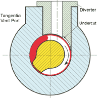
When melt accumulates in the vent port, it will eventually plug the port. The solution is to modify the opening below the vent to allow for normal swelling of melt in the vent area. If the expansion of the rolling bank, for example, is as much as 0.2 to 0.4 in., the depth of this relief area should be at least that much.
Bad vent design
To take an example from real life, an overseas sheet extruder recently experienced vent-flow problems so severe that the plant couldn’t produce sheet of acceptable quality. The problem was experienced on a newly refurbished, 6-in., single-screw extruder with venting to remove moisture from ABS.
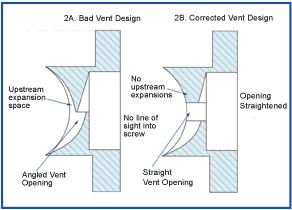
Operators tried to check the level of melt in the screw channel under the vent port, but found the vent port insert or diverter was designed so that it was impossible to look all the way in (Fig. 2). This was the first indication that the diverter was poorly designed. The processor had to remove the insert to check how full the screw channel was. It turned out to be only about 40% full, indicating that the screw was working correctly.
The troubleshooting process then focused on the design of the diverter. Even though a reputable extruder manufacturer had supplied the diverter, its design was seriously flawed. When the diverter was examined, it was found to have an undercut not only downstream from the vent opening to allow for normal expansion, but also upstream. The undercut upstream was not only unnecessary, it was detrimental because it increased exposure time of the melt pool to the port opening and allowed the melt pool to expand too much, increasing the buildup of melt at the vent port.
Another problem was the horizontal or tangential vent opening, which is harder to clean than a straight one. In a proper diverter, the vent opening is perpendicular to the radius of the barrel.
The diverter therefore was modified in two ways. First, the upstream undercut was filled with metal. Second, the tangential opening was changed to a radial orientation, allowing an operator to see the melt in the screw and also making the port easier to clean. Fortunately, these modifications eliminated the vent-flow problem, and the processor was able to produce good-quality sheet.—Edited by Jan H. Schut
Related Content
Extrusion Excellence: This Year's Top Stories
Revisit the year’s most popular articles on extrusion technology and processes, showcasing innovations, best practices, and the trends that captured the plastics processing community’s attention.
Read MoreBrewer Chooses Quick-Change Flexibility to Blow Wide Range of PET Beer Bottles
Beermaster Brewery found a “universal” stretch-blow machine from PET Technologies enables multiple changes per day among four sizes of beer bottles.
Read MoreHow to Effectively Reduce Costs with Smart Auxiliaries Technology
As drying, blending and conveying technologies grow more sophisticated, they offer processors great opportunities to reduce cost through better energy efficiency, smaller equipment footprints, reduced scrap and quicker changeovers. Increased throughput and better utilization of primary processing equipment and manpower are the results.
Read MoreHow to Decrease the Extrudate Temperature in Single-Screw Extruders
In many cases, decreasing the discharge temperature will improve product quality and perhaps even boost rate. Here are ways to do it.
Read MoreRead Next
Beyond Prototypes: 8 Ways the Plastics Industry Is Using 3D Printing
Plastics processors are finding applications for 3D printing around the plant and across the supply chain. Here are 8 examples to look for at NPE2024.
Read MorePeople 4.0 – How to Get Buy-In from Your Staff for Industry 4.0 Systems
Implementing a production monitoring system as the foundation of a ‘smart factory’ is about integrating people with new technology as much as it is about integrating machines and computers. Here are tips from a company that has gone through the process.
Read MoreSee Recyclers Close the Loop on Trade Show Production Scrap at NPE2024
A collaboration between show organizer PLASTICS, recycler CPR and size reduction experts WEIMA and Conair recovered and recycled all production scrap at NPE2024.
Read More


