How to Mold Long Fiber Reinforced Thermoplastics
Here’s the machinery, tooling, and process know how you need to get the most out of these high-performance materials.
Long fiber reinforced thermoplastics (LFRTs) are being used in injection molding applications that demand a high level of mechanical property performance. While LFRT technology is capable of excellent strength, stiffness, and impact properties, how these materials are processed plays a major role in determining how much of that performance ends up in the part.
In order to successfully mold LFRTs, it is important to have a basic understanding of what makes them unique. Understanding the differences between LFRTs and conventional reinforced thermoplastics drives the equipment, design, and processing decisions that maximize the benefits and potential of LFRTs.
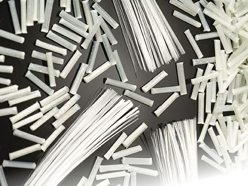
The difference between LFRTs and conventional chopped, short glass fiber reinforced compounds lies in the length of the fibers. In LFRTs, the length of the fiber is the same as the length of the pellet. This is due to the fact that most LFRTs are produced via a pultrusion process, rather than shear-intensive compounding. In LFRT manufacturing, continuous strands of glass-fiber rovings are pulled through a die, where they are coated and impregnated with thermoplastic resin. This continuous rod of reinforced plastic is then chopped or pelletized, typically to lengths of 10-12 mm. In contrast, conventional short glass compounds incorporate chopped fibers 3-4 mm long that have been further reduced to typically less than 2 mm in a shear-intensive extruder.
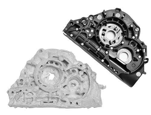
The length of the fiber encased in the LFRT pellet contributes to the improved mechanical properties of LFRTs. Impact resistance, or toughness, is increased while maintaining stiffness. As long as the fibers remain long throughout the molding process, they create an “internal skeleton,” providing the mechanical performance for which they are noted. However, a poor molding process can convert a long fiber product into a short fiber material. If the length of the fiber is compromised in the molding process, the level of performance that is possible and desired may not be achieved.
In order to maintain fiber length throughout the molding of LFRTs, there are three important areas to consider: the injection molding machine, part and tool design, and processing conditions.
EQUIPMENT CONSIDERATIONS
One commonly asked question regarding LFRT processing is whether it is possible to use existing injection molding equipment to mold these materials. In the vast majority of cases, equipment used to mold short fiber compounds can also be used to mold LFRTs. While typical short fiber molding equipment is adequate for most LFRT parts and products, some equipment modifications can be made to help preserve fiber length.
A general purpose screw with the typical “feed-compression-metering” zones can work well for the process, though fiber-damaging shear may be reduced by lowering the compression ratio of the metering section. A metering section compression ratio of about 2:1 is excellent for LFRT products. Screws, barrels, and other equipment made from special metallic alloys are not necessary, as LFRTs are no more abrasive than traditional chopped-glass reinforced thermoplastics.
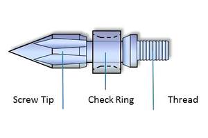
The other piece of equipment that may benefit from a design review is the nozzle tip. Some thermoplastic materials process more easily with a reverse-taper nozzle tip, which can create a high degree of shear as material is injected into the mold cavity. This type of nozzle tip would significantly degrade fiber length of a long fiber compound. A 100% “free-flow” fluted nozzle-tip/valve assembly is recommended to allow easy passage of the long fibers through the nozzle and into the part. Additionally, the nozzle and sprue orifice should have generous dimensions of 5.5 mm (0.250 in.) diam. or more and be free of sharp edges. It is important to understand how the material flows through the injection molding equipment and to identify places where shear would try to break down the fibers.
PART AND TOOL DESIGN
Good part and tool design practices will also go a long way toward maintaining the fiber length of LFRTs. Eliminating sharp corners around the edges of the part (including ribs, bosses, and other features) avoids unnecessary stresses in the molded part and reduces fiber attrition, as well.
The part should be designed with a nominal wall—a consistent, uniform wall thickness throughout. Large variations in wall thickness can result in inconsistent filling and undesirable fiber orientation in the part. In places where thicker or thinner walls are necessary, avoid abrupt changes in wall thickness, which can create high-shear areas that may damage fibers, and be a source of stress concentration. Always try to gate into the thicker walls and flow toward thin sections, keeping the thin sections for the end of fill.
Good general plastic design principles suggest that keeping wall thicknesses below 4 mm (0.160 in.) will promote good, uniform flow and reduce the possibilities of sinks and voids. For LFRT compounds, the optimal wall thickness is typically about 3 mm (0.120 in.), with a minimum thickness of 2 mm (0.080 in.). Wall thicknesses less than 2 mm increase the probability of fiber breakage after the material has entered the tool.
Part design is only one aspect of the tooling; it’s also important to consider how the material gets to the mold. As the runners and gates guide the material to the mold cavity, a lot of fiber degradation can take place in these areas if they are not properly designed.
When designing a tool for use with an LFRT compound, full-round runners are preferred, with a minimum diameter of 5.5 mm (0.250 in.). Anything other than a full-round runner will have sharp corners, which can increase stress and damage to the glass-fiber reinforcement during molding. Open channel hot-runner systems are acceptable.
Gates should have a minimum thickness of 2 mm (0.080 in.). If possible, locate the gate along an edge where it has unimpeded flow into the cavity. Gates into the face of the part will require a 90° turn, inviting fiber breakage and reducing mechanical performance.
Finally, be aware of the location of knit lines and how they relate to the areas of the part that will be under load (or stress) when in use. Care should be taken with gate placement to move those knit lines to areas where stress levels are expected to be lower.
A computer mold-filling analysis can help identify where those knit lines will be located. A structural finite element analysis (FEA) can be used to compare locations of high stress to the locations of the knit lines identified in the mold-filling analysis.
It should be noted that these part and tool design recommendations are just those—recommendations. There are plenty of examples of parts with thinner walls, wall-thickness variations, and fine or detailed features that achieve good performance utilizing LFRT compounds. However, the further one strays from these recommendations, the more time and effort will be required to ensure that the full benefit of long fiber technology will be realized.
PROCESSING CONDITIONS
Processing conditions are the key to success with LFRTs. It is possible to make good parts from LFRT materials using a general purpose injection machine and properly designed tools as long as the right processing conditions are used. However, even with the proper equipment and tool design, fiber length can suffer if poor processing conditions are employed. Again, be mindful of the conditions the fibers will encounter as they go through the molding process and identify areas that can cause excessive shear.
First, monitor the backpressure. High backpressures introduce a tremendous amount of shear force on the material and will reduce fiber length. Consider starting with zero backpressure and increase it only to the point where the screw comes back evenly and consistently during feeding. A backpressure of 1.5 to 2.5 bar (20-50 psi) is typically enough to get consistent feeding.
High screw speeds can also have a detrimental effect. The faster the screw turns, the higher the chances that solid and unmelted material will enter the screw compression zone and cause fiber damage. Similar to the suggestion for backpressure, try keeping the screw speed at the minimum level required to fill the screw consistently. Screw speeds of 30 to 70 RPM are common when molding LFRT compounds.
In the injection molding process, melting takes place via two factors that work together: shear and heat. Since the intention is to preserve fiber length in LFRTs by reducing shear, then more heat will be required. Depending on the resin system, it‘s not uncommon for LFRT compounds to be processed 10-30° F higher than conventional molding compounds.
However, before simply increasing barrel temperatures across the board, try reversing the barrel temperature profile. Normally, barrel temperatures rise as the material moves from the hopper to the nozzle; but for LFRTs, higher temperatures at the hopper are recommended. Reversing the temperature profile will soften and melt the LFRT pellets before they enter the high-shear region of the screw’s compression zone. This can go a long way toward improving fiber-length retention.
The last item regarding processing relates to the use of regrind. Grinding up molded parts or runners usually results in much lower fiber length; thus, regrind cannot be added without compromising overall fiber length. A maximum level of 5% regrind can be used without significantly reducing mechanical properties. Higher levels of regrind will negatively affect impact strength and other mechanical performance.
Related Content
Ultrasonic Welding: Tips, Techniques, and Troubleshooting
In this collection of content, we provide expert advice on welding from some of the leading authorities in the field, with tips on such matters as controls, as well as insights on how to solve common problems in welding.
Read MoreGot Streaks or Black Specs? Here’s How to Find and Fix Them
Determining the source of streaking or contamination in your molded parts is a critical step in perfecting your purging procedures ultimately saving you time and money.
Read MoreThe Effects of Stress on Polymers
Previously we have discussed the effects of temperature and time on the long-term behavior of polymers. Now let's take a look at stress.
Read MoreMedical Tubing: Use Simulation to Troubleshoot, Optimize Processing & Dies
Extrusion simulations can be useful in anticipating issues and running “what-if” scenarios to size extruders and design dies for extrusion projects. It should be used at early stages of any project to avoid trial and error and remaking tooling.
Read MoreRead Next
See Recyclers Close the Loop on Trade Show Production Scrap at NPE2024
A collaboration between show organizer PLASTICS, recycler CPR and size reduction experts WEIMA and Conair recovered and recycled all production scrap at NPE2024.
Read MorePeople 4.0 – How to Get Buy-In from Your Staff for Industry 4.0 Systems
Implementing a production monitoring system as the foundation of a ‘smart factory’ is about integrating people with new technology as much as it is about integrating machines and computers. Here are tips from a company that has gone through the process.
Read MoreMaking the Circular Economy a Reality
Driven by brand owner demands and new worldwide legislation, the entire supply chain is working toward the shift to circularity, with some evidence the circular economy has already begun.
Read More
