How to Troubleshoot Your Feeder to Achieve Optimal Performance
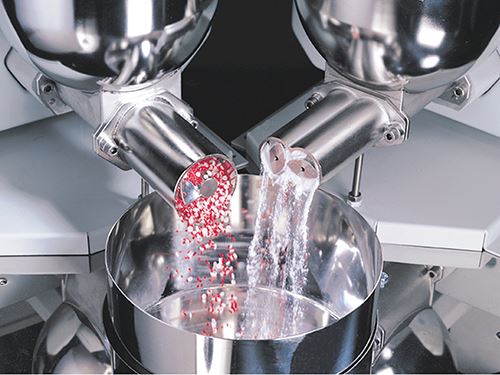
Even the tiniest improvements in compounding feeder accuracy can improve profits. Here’s how to keep your feeding system in the pink.
In today’s tough global economy, the pressures for proper maintenance, increased longevity of process equipment, and optimal performance are higher than ever before. Compounding feeders that don’t feed accurately typically produce off-spec finished products and require extended periods of downtime to recalibrate or fix, resulting in decreased production rates and lost profits. In all industries, the improvement in accuracy performance by even 0.025% of ingredient feeding can result in significant overall profits.
Proper installation, ideal weighing configurations, and appropriate choice of weighing controls can result in the avoidance of a variety of future feeder problems. For a complex feeder system—such as multiple loss-in-weight (LIW) feeders feeding powder and pellets into mixers or extruders—external influences such as vibration, platform stability, and upstream/downstream equipment connections can all affect a feeder’s performance. Informed knowledge of the significance of these influences is key to optimizing its performance. By thoroughly training your operating and maintenance workers and keeping them familiar with effective troubleshooting and maintenance practices, a variety of these problems can be mitigated.
Feeders are typically engineered to address a specific material at a specific discharge rate. Changes in material, operating conditions (such as ambient or material temperatures), plant vibration levels, as well as changes in material characteristics, can all affect feeder performance. Choosing a feeder that can be easily reconfigured in your plant to handle new conditions can help you solve these problems.
By definition, most feeders can be categorized as volumetric or gravimetric. This article will investigate both types and review the significance of a number of parameters and their direct influence on feeder performance. The following sections discuss the operation of common feeder technologies and explain how to optimize a feeder based upon its operating principles.
VOLUMETRIC SCREW FEEDERS
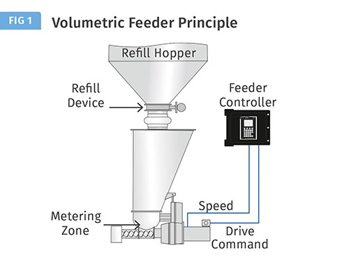
A volumetric screw feeder (see Fig. 1), feeds a certain material volume per unit time (such as ft3/hr) to a process. The volumetric screw feeder consists of a hopper, material-discharge device, and controller. This is the most common volumetric feeder, and its material-discharge device is a screw that rotates at a constant speed to meter material at a predetermined volume-per-revolution discharge rate from the hopper to the process. The controller monitors and controls the feeder's screw speed, which determines the discharge rate of the material.
An optimal agitation system located between the hopper and the screw can facilitate material discharge from the hopper. Various agitation systems and screw designs, sizes, and geometries are available to suit your application. Because the volumetric screw feeder cannot detect or adjust to variations in a material's bulk density, the feeder is most effective with relatively free-flowing uniform-density materials, such as pellets, and in applications where high feeding accuracy is not crucial.
Volumetric screw-feeder problems are relatively easy to diagnose. Most problems relating to the feeder's discharge rate stem from a faulty screw-speed control sensor or motor drive, a change in the discharge rate's volume-per-revolution ratio, or material flow problems from the hopper. Precise control of the discharge rate will be impossible if the feeder's screw-speed control sensor doesn't register the screw speed accurately (or at all). If the feeder's discharge rate is a problem, first check for loose sensor wiring and electrical connections. If the connections are sound, you may need to clean or replace the sensor. You can easily evaluate the sensor if the motor speed is stable.
If the screw-speed sensor is not causing the problem, then the cause is probably a change in the discharge rate's volume-per-revolution ratio. Such a change is typically caused by material buildup on the screw or in the discharge tube or by a blockage in the hopper that prevents consistent material supply to the screw. The buildup or blockage reduces the material volume that the screw discharges in each revolution at a constant screw speed. An immediate, but temporary, remedy is to clean the screw, discharge tube, hopper, or all three. To permanently solve the problem, you may have to change the screw or hopper design or add an agitation system to help move material from the hopper to the feed screw. Coating or polishing the internal metal surfaces may also alleviate the problem, but consult with your manufacturer for guidance.
BASICS OF LOSS-IN-WEIGHT FEEDING
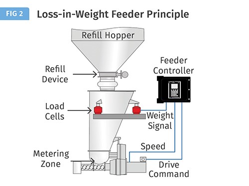
Unlike the volumetric screw feeder, a continuous loss-in-weight (LIW) feeder is a gravimetric feeder that directly measures the material’s weight to achieve and maintain a predetermined feed rate that’s measured in units of weight per time. The LIW feeder (see Fig. 2), consists of a hopper, refill device, weight-sensing device (typically either a digital or analog scale or load cells), material-discharge device (typically a volumetric screw feeder powered by a variable-speed motor), and a controller. Before operation, an operator programs the controller to discharge material at a predetermined feed rate (or setpoint) measured in units of weight per time (such as lb/hr).
The bulk material or liquid is discharged from a hopper with a constant weight per unit time by weighing the hopper and regulating the speed of the feeding device depending on the rate of weight loss. The weighing control system compensates for non-uniform material-flow characteristics and variations in bulk density, thus providing a high degree of feeding accuracy. When the hopper reaches a predetermined minimum weight level, the LIW control is briefly interrupted and the hopper is refilled. With some manufacturers, during the refill period, the controller regulates the speed of the feeding device based upon the historic weight and speed information that was accumulated during the previous weight-loss cycle. This prevents overfeeding of material during the refill cycle due to changes in headload of material and filling of material into the screws. This is also critical for maintaining feed-rate performance within specification on a second-to-second basis. The LIW feeding principle is most accurate when using a high resolution, fast-responding, and vibration- and temperature-immune weighing system.
LIW feeder performance is dependent on three factors that are closely linked:
- The mechanical configuration of the feeding device and any material flow aid used in the feeder hopper;
- The accuracy and speed of weight measurement and the immunity of the weighing system to in-plant vibration and temperature fluctuations;
- The response of the control algorithm and the available features of the control algorithm.
VALIDATING LIW FEEDER CONFIGURATION
The mechanical feed device selected and the configuration of the feed device is the starting point in any LIW feeding system. Some typical feed devices are as follows:
• Single-screw feeders can be applied when feeding granular free-flowing materials. When running at lower setpoints, single-screw feeders may produce a pulsating discharge that will affect second-to-second performance. Some suppliers have developed software to compensate for this pulsation and achieve consistent accuracy.
• Twin-screw feeders can be applied when feeding hard-to-flow and sticky materials and reduce the pulsating discharge even at lower feed rates.
• Vibratory trays for granular free-flowing materials provide a uniform discharge.
Single- and twin-screw feeders have different screw profiles and configurations that can be tailored to the material being fed as well as the setpoint turndown requirements. The key is to select the proper feeder and configuration to give the most uniform and reliable volumetric feeding of the material. By doing this, the weighing and control system does not have to work as hard to provide optimal performance.
The same holds true for any flow-aid device that may be required in the feeder’s hopper. This will ensure that the material flows into the feeding device as uniformly as possible. Stability of the feeding system allows the weighing and control system to provide optimal second-to-second performance.
There are several types of material flow aids available:
• Flexible-side-wall feeders gently agitate materials. However, these are not stainless-steel surfaces and may wear or create contamination concerns.
• Mechanical hopper agitators stir the material and break down any bridging or rat-holing of the material. However, these devices require additional headroom for the feeder and may become a cleaning concern.
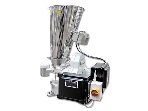
• Applying vibration to the hopper is another option, however if not properly regulated, this could pack the material in the hopper. A new technology, called ActiFlow, applies vibration to the hopper using an external drive at a variable frequency and amplitude based upon the weighing and control system detecting non-uniform material flow by weight. This technique eliminates headroom and cleaning concerns and avoids compaction of the process material because only the necessary amount of vibration is applied to ensure uniform material flow (see photo).
Any LIW process controller requires accurate high-speed measurement of material weight changes in order to provide optimal feeder control and performance, especially on a second-to-second basis. The weighing system must also be able to filter out erroneous measurements due to in-plant vibrations or disturbances and must be stable over changes in ambient or material temperatures.
There are two types of weighing technology typically used in LIW feeders: analog strain-gauge technology and digital vibrating-wire technology. The key is that the higher the resolution of weight measurement and the faster those weight measurements are taken, the better the information that will be provided to the control algorithm and the better any vibration-filtering algorithm will work. Almost all weighing systems provide temperature compensation, but it should be verified over the temperature range of your application, as this can affect the long-term stability of feeder performance.
TROUBLESHOOTING & IMPROVING LIW FEEDER PERFORMANCE
Because the LIW feeder typically uses a volumetric screw feeder to meter material, many of the volumetric feeder problems and solutions already covered also apply to the LIW feeder. But since the LIW feeder’s operation is based on the weight-loss rate per unit time rather than the screw speed, the controller automatically compensates for material buildup on the screw or in the discharge tube, or a blockage in the hopper, by increasing the screw speed to maintain the set-point. The controller continues to increase the screw speed until the feeder reaches an alarm condition, such as when the screw speed exceeds the recommended operating speed. If an alarm condition occurs in your LIW feeder, check first for material buildup on the screw or in the discharge tube or a blockage in the hopper. Understanding and properly configuring your controller’s alarm settings will allow the user to perform preventive maintenance prior to a catastrophic failure. If you find no material buildup or blockage, check the hopper to ensure that it has material in it. If the hopper is empty, you then need to check the upstream material delivery system for a blockage or other malfunction.
The LIW feeder’s operation depends on accurate weight measurements of the material in the hopper and vibration can impose artificial forces on the feeder that cause weighing errors. Therefore, make sure the feeder and weight-sensing device are isolated from any external vibration created by other equipment in your process. This requires installing the feeder so that the weight-sensing device is shielded from vibration effects. Do this by ensuring that the feeder has a stable mounting, using flexible connections and shock mounts, and by eliminating strong air currents near the feeder.
Vibration problems can result later from installing new equipment near the feeder or improperly refitting the feeder’s flexible connections during maintenance. For example, if your LIW feeder has feed-rate problems that appear to correlate with the operation of newly installed machinery or that occur after feeder maintenance, external vibration is probably affecting the weight-sensing device. To solve these problems, you need first to make sure that the feeder and weight-sensing device are isolated from any vibration created by the newly installed equipment. Or, if the problems occur after maintenance, recheck the flexible connections to ensure that they’re properly connected to the feeder.
The weight-sensing device itself can cause performance problems if you don’t select it properly for your application. Carefully evaluate the weight-sensing device’s capabilities—such as resolution, stability, responsiveness, weight-signal integrity, vibration sensitivity, reliability, and data communications—before purchasing the LIW feeder. After installing your feeder, maintain its performance and find any problems such as drift (a gradual deviation from a set adjustment) as early as possible by regularly calibrating the weight-sensing device.
Other performance problems can result from a defective refill device or a leaky seal at the feeder’s discharge. If an automatic refill device loads material into the hopper, any leakage in the refill device at the hopper’s inlet will produce a feed-rate error because material will continue leaking into the hopper after the refilling process has stopped. This creates a weight-loss rate change; the controller senses that not enough material is being discharged from the hopper. To compensate for this, the controller increases the screw speed to meet the setpoint, discharging more material per unit time.
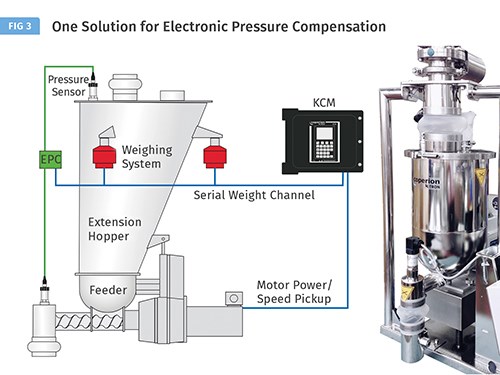
Also, if the LIW feeder discharges material to a non-ambient-pressure environment such as a pressurized or vacuum conveying line, a pressure pulse (air leaking from the downstream system through the feeder’s discharge tube to the weight-sensing device) can cause a feed-rate error. A pressure pulse affects the hopper’s instantaneous weight measurement by exerting a vertical force on the weight-sensing device opposite to the hopper’s downward force, in effect, slightly lifting it so that its weight reads lower. Traditionally the solution is a complex arrangement of pipes and flexible connections to compensate for known pressure differentials within the system. As an alternative to traditional mechanical compensation systems, instrumentation and control algorithms to electronically monitor and compensate for pressure influences can be supplied.
An innovative electronic pressure-compensation system, such as Coperion K-Tron’s Electronic Pressure Compensation (EPC), can be used to automatically detect changes in pressure within the feeder hopper or outlet tube and adjust the weight signal accordingly to compensate for any errors caused by pressure fluctuations (see Fig. 3).
ABOUT THE AUTHOR: John Winski is the dir. of sales for Coperion K-Tron, Sewell, N.J., a leading worldwide supplier of feeding equipment for plastics and other industries. He is responsible for sales in the Americas for Coperion K-Tron feeders, pneumatic conveying, and engineered systems. He has 28 years of experience at Coperion K-Tron and has held positions as a service engineer, project engineer, and regional sales manager. Contact: (856) 589-0500; JWinski@coperionktron.com; coperionktron.com.
Related Content
Safety, Recycling, and Compounding Trends Bring New Opportunity to 70-Year-Old Company
NPE2024: Vac-U-Max presents pneumatic conveying solutions for powdered materials.
Read MoreGravimetric Feeder is Compact, Easy to Clean
Said to offer precise rate control for free-flowing pellets and granules.
Read MoreFeeders Now Furnished With Portable Touchscreen Controller
New portable controller maintains functionalities of previous controller while introducing significant enhancements.
Read MoreHow to Effectively Reduce Costs with Smart Auxiliaries Technology
As drying, blending and conveying technologies grow more sophisticated, they offer processors great opportunities to reduce cost through better energy efficiency, smaller equipment footprints, reduced scrap and quicker changeovers. Increased throughput and better utilization of primary processing equipment and manpower are the results.
Read MoreRead Next
See Recyclers Close the Loop on Trade Show Production Scrap at NPE2024
A collaboration between show organizer PLASTICS, recycler CPR and size reduction experts WEIMA and Conair recovered and recycled all production scrap at NPE2024.
Read MoreMaking the Circular Economy a Reality
Driven by brand owner demands and new worldwide legislation, the entire supply chain is working toward the shift to circularity, with some evidence the circular economy has already begun.
Read MoreFor PLASTICS' CEO Seaholm, NPE to Shine Light on Sustainability Successes
With advocacy, communication and sustainability as three main pillars, Seaholm leads a trade association to NPE that ‘is more active today than we have ever been.’
Read More
