In-Line Radar-Based Measurement of Extruded C900 PVC Pipe Reduces Material Cost, Improves Quality
Sponsored ContentNew radar-based measurement technology enables processors to extrude higher-quality pipe with less material. With an automated closed-loop control system you’ll get more output and less scrap to significantly lower costs.
Share
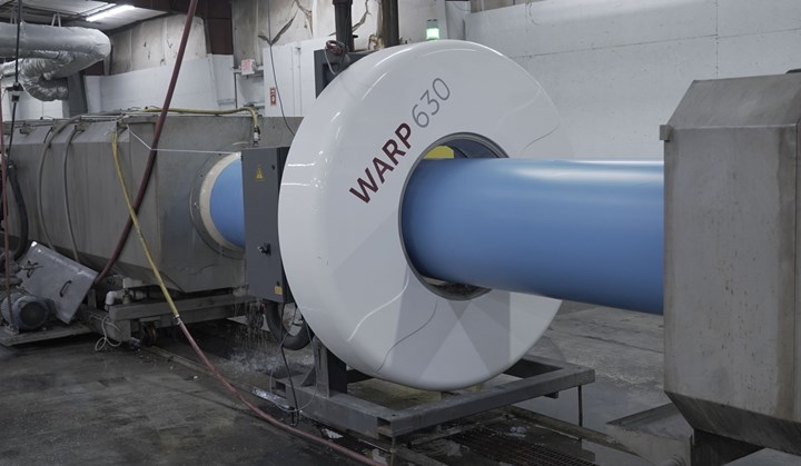
iNOEX WARP measuring system on Jet Stream’s C900 PVC pipe extrusion line.
Extruding municipal piping often tends to be more art than science. Actually, that’s a nice way to say that without reliable measurement instruments and process controls, processors are forced to use cruder methods of quality control that are cumbersome and typically result in higher material consumption rates than necessary to consistently produce pipes which meet all relevant industry standards.
New radar-based in-line measurement systems from iNOEX finally bring real time data-based process control to the pipe extrusion process. With the ability to precisely measure pipe wall thickness, diameter and roundness, these systems enable processors to reduce the amount of material required to meet the most demanding quality standards and reduce scrap while virtually eliminating the production of non-conforming product. Moreover, by integrating the measurement system with iNOEX gravimetric feeders you can close the loop in an automated system that automatically adjusts for process drift to keep the line running consistently day after day. You can even improve throughput by feeding material at the same rate while increasing the haul-off speed. Here’s how it works.
Accurately Measuring Wall Thickness Is the Key
iNOEX’s WARP radar sensor measuring systems use radar technology to precisely record all relevant dimensions of a pipe on the basis of echo detections. No contact coupling medium is required to transmit and receive the radar waves, which makes the device very robust, reliable and independent of process fluctuations.
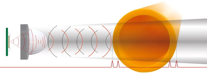
Radar measurement works by emitting an electromagnetic wave at an object and capturing the time elapsed between echoes as the wave encounters external or internal surfaces.
In operation, a radar sensor works on the time-of-flight principle to calculate very precise physical measurements. A sensor unit sends out an electromagnetic wave which echoes back when it hits an object in its path. In pipe extrusion the first echo comes when a pulse hits the pipe OD, the second when it hits the ID wall (or more precisely, the air behind it), and then it repeats on the opposite side of the pipe. By measuring the time elapsed between transmission and echoes, very fast and precise dimensional measurements can be calculated for wall thicknesses as small 0.200” (5 mm). Measurements are generated with an accuracy of ±0.002” (0.05 mm) and repeatability of ±0.004” (0.102 mm) even at line speeds up to 50 feet per minute (15 m/min).
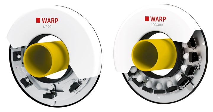
The WARP 8 series use 8 sensors and measures pipe dimensions from 60 to 1200 mm (2.26-47.24”) in diameter. More sensors are available on special request. The WARP 100 series places sensors closer together to provide 100% measurement around the circumference of the pipe to meet the highest quality standards for pipe ranging from 90 to 630 mm (3.54-24.80”) in diameter.
WARP measurement units include an array of these sensors positioned around the circumference of the pipe, which can be placed in multiple locations on an extrusion line. WARP 8 systems provide real-time measurements of wall thickness and diameter at 8 points around the pipe, and more sensors can be used on special request. For applications with the most stringent quality inspection requirements, WARP 100 units use more sensors to enable 100% measurement around the circumference of the pipe as well as the extrusion direction and can also detect eccentricity and ovality.
With this measurement data, pipe manufacturers will finally have a robust and user friendly tool that will allow them to see the true variation in their extrusion processes for the first time. Once a repeatable process spread is established, material feed or haul off speed can be tuned so that the minimum amount of material is used to produce pipe that is 100% compliant with quality standards. This is what enables processors to safely run more closely to the lower limit of required wall thickness, which delivers big material savings on a high-volume extrusion line.
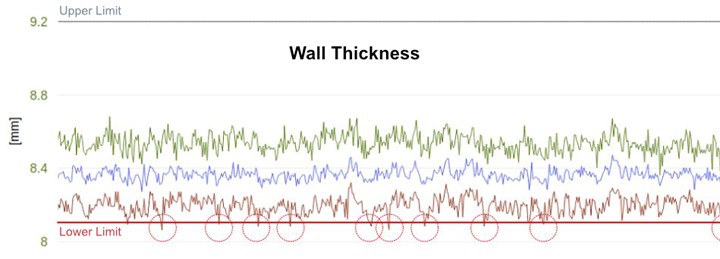
WARP technology reveals the true variability of a pipe extrusion process. This is a continuous measurement of wall thickness with the spread shown in the green and brown graphs and the average in blue. Once the variability spread is known the process can be adjusted to run closer to the lower tolerance limit (red line) to save material. It also displays instances where wall thickness is below spec (red circles), or above, so adjustments can be made to continuously extrude conforming product.
iNOEX says average savings of 2% or more are common with a payback on the investment in the measuring technology of about a year on material savings alone at historical raw material costs, and the payback is even faster given the current market pricing of raw materials. But that’s not the only savings. The measurement data enables processors to get their lines producing in-spec product more quickly at the start of a run, and it will detect process drifts early on so that problems can be discovered and corrected before any bad product is made. Both factors can result in major reductions in scrap.
Moreover, as less material is required to produce consistently conforming product, you can continue to push material into the system at the same or similar rate and increase the haul-off speed. That increases throughput of the extrusion line typically in the range of 2%. More pipe with less material is an excellent formula for a more profitable line.
The next level of this technology is to integrate the measurement system with an iNOEX gravimetric feeder to achieve automated closed-loop process control. The system will now be able to self-monitor how it is running compared to established set points and automatically adjust the feed volume or haul off speeds if the process starts to drift, maintaining quality and stability without need for human intervention. More on this below.
Case in Point
Jet Stream is among the world’s foremost manufacturers of construction grade pipe systems. One of the specialties that Jet Stream makes in its Siloam Springs, Arkansas plant is C900 PVC pipe for high pressure water distribution. Pipe extruders will know that this is among the most demanding applications for large diameter pipe (Jet Stream’s C900 diameter range is 4-24”) and producing non-conforming pipe is flatly unacceptable.
This video explains why Jet Stream decided to move to radar measurement in a closed loop control system and the results they’ve achieved so far.
Before having a WARP radar system (see video) Jet Stream did not have a good means to measure critical pipe attributes during production. Instead, they relied on inspection after pipe was sawed to final length. Their C900 line is quite long with two cooling tanks, a haul-off unit and sawing station after the vacuum tank. So a lot of material was already in process if a problem was detected in inspection.
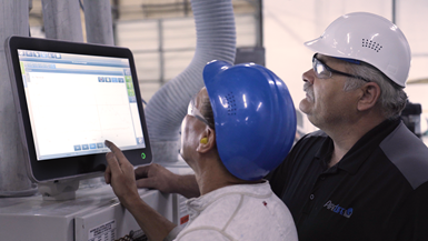
The WARP system shows operators how the line is running which enables them to correct for excess material usage or emerging process drifts.
Once Jet Stream installed a WARP unit right after the vacuum tank they could now see what was happening in the process in real time. According to assistant plant manager, Paul England, they can see impending problems immediately and adjust for them before non-conforming product is produced. Moreover, England says they can see how their process spread looks relative to the tolerances and adjust so they “don’t give away all this free material.” Jet Stream has also found that the measurement data enables them to get startups producing good pipe more quickly. Plant manager, Louie Bold, says that the initial projections on the payback for the system were very accurate. Through material savings and reduced scrap, it is “paying for itself” he says.
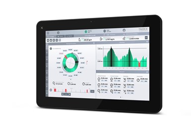
The WARP dashboard provides an easy-to-understand picture of all measured features of a pipe extrusion process and shows when and where non-conforming events occur.
Making Measurement Easy
Major drawbacks of inline measurement systems of the past have been that they can be difficult to use, maintain and keep stable over time. For example, ultrasonic systems need a water coupling medium to work, requiring contact seals on the pipe to retain the water. Those are wear parts, and changing pipe diameter requires changing out the seals as well. X-ray systems are non-contact, but they emit radiation at levels some users are uncomfortable with and are impractical for larger diameter products.
The WARP systems are non-contact and the electromagnetic waves they emit have less human impact than a cell phone. Across the product line, they can be used for pipe from 60 mm (2.36”) to 1200 (47.24”) mm in diameter. A single measuring system can accommodate pipe from 4 to 7 times the minimum pipe diameter (depending on the model). To start a new run, the operator just has to call up the preprogrammed product recipe with with the appropriate pipe specs and then hit start. Since the donut-shaped measuring sensor is self-centering, and will automatically recenter itself if needed, there is no need for recalibration for each product or during long production runs.
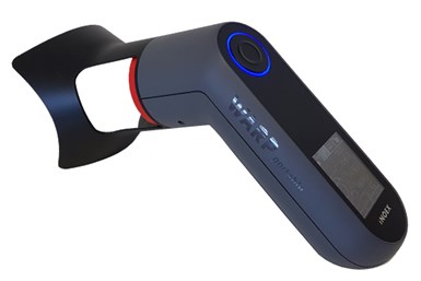
Radar measuring technology is also available in a hand-held version called WARP Portable. For wall thicknesses from 0.200-4.33” (5 to 110 mm), the instrument includes data logging with time stamp and measurement position on pipe circumference.
The easy-to-understand control dashboard is web-enabled so it can be viewed on a mobile device in the plant or anywhere in the world. It displays graphically and numerically:
- Pipe diameter
- OD & ID dimensions
- Wall thickness
- Eccentricity and ovality
- Total throughput per hour
- Total weight per meter of pipe
- Haul-off speed
It even shows specifically where any problems are occurring. In the example image above you can see an instance where wall thickness dropped below the setpoint, shown in red in the bar chart, and where it exceeded the maximum limit, shown in black. In the circle chart to the left, you can see precisely where around the circumference of the pipe those events occurred.
The system also generates reports to provide a historical look at extrusion line performance. This can be enormously useful in process optimization projects and in quality validation reports to assure customers that products are meeting performance requirements.
Closing the Loop
Integrating the measuring system as Jet Stream has done with an iNOEX gravimetric feeder provides a level of automation that was not really possible before. With this step the measuring system can automatically calculate the most material-efficient way to manage the process. Known as thin point control, in this scenario pipe is measured in process after emerging from the vacuum tank. First making sure the process is stable and in compliance with the wall thickness spec, the thinnest point will define the control step. Algorithems then calculate a new weight per meter set point to meet the minimum acceptable wall thickness spec.
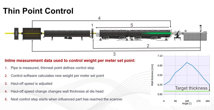
Thin point control can automatically calculate the most material-efficient way to manage the process and adjust feed or haul off speed accordingly. See full size image.
Rather than reducing the material feed rate, the control can automatically increase the haul-off speed. This obviously saves on material cost but the increased haul-off speed also means you are producing more meters of sellable pipe per units of time and material. This increase will typically boost throughput in the range of 2 percent, depending on how much material reduction is achieved.
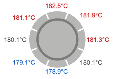
WARP thermal die head centering control can be applied to manipulate melt speeds directly at the die to reduce eccentricity.
Another automation option is using WARP with thermal die head centering control. In this case you need a sliced die head with individual temperature zones. At startup, each zone has the same temperature. With the sensor you are able to detect thermally induced eccentricity by measuring the wall thickness distribution. With this data the control can compensate by manipulating melt speeds directly at the die head by calculating new temperature setpoints for each zone.
This real case study demonstrates how effective the combination of these measurement and control loops can be. The graph here illustrates the optimization of an extrusion line making 250 mm diameter (10”) PVC pipe with a 5.9 mm (023”) wall thickness. At the left of the graph you can see the initial distribution of the max and min wall thickness relative to the upper and lower tolerances. In order to continuously meet the minimum tolerance, the processor had no choice but to use a lot of material, which at times drove wall thickness over the max tolerance.
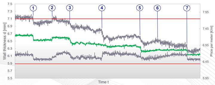
Process improvement process for 250 mm PVC pipe line. See full size image.
Here are the steps taken to optimize the process.
- Thin point control is applied. Haul-off speed is increased, and wall thickness is decreased.
- Throughput is increased which drives wall thickness up again.
- Thin point control is again applied, increasing haul-off speed and reducing wall thickness.
- A manual recentering step is applied which substantially reduces variability in the process.
- The narrowed variability range provides a new opportunity for thin-point control to bring the entire process closer to the minimum tolerance, further reducing material usage and increasing haul-off speed. Thermal die head centering control is started to reduce remaining eccentricity.
- While thermal die head centering is working to reduce eccentricity, it initially causes a slight rise in max wall thickness. As the system learns, however, as the variability band continues to narrow.
- Once variability has grown sufficiently small the process is adjusted again to achieve an optimal combination of specification conformity and material use.
In this case, the closed loop systems resulted in an average material cost reduction of about 9%. iNOEX is quick to point out that this is an extreme case, but it nonetheless illustrates what this technology can do. In more common applications they conservatively project a system will routinely produce a 2% reduction in material cost or more and increase output by a similar amount.
The economics of radar-based measurement and closed loop control will make sense for a wide variety of pipe manufacturers with many achieving paybacks within a year. Reduced material cost + increased output + higher quality pipe is a formula that is tough to beat.
Please go here for more information on iNOEX WARP radar-based measuring systems.
